Expert Tips
Hybrid Design: Mass Timber Floor and Roof Panels Over Light-Frame Wood Walls
Explores construction type and fire-resistance ratings, lateral system options, and acoustic performance
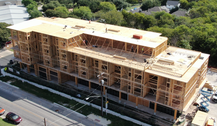
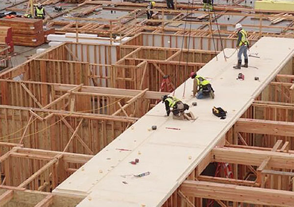
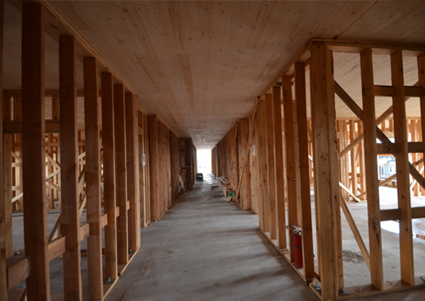
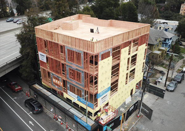
One of the more recent developments in mid-rise multi-family design is the merger of mass timber and light-frame wood construction—typically light-frame bearing walls supporting mass timber floor and roof panels. The walls are the same as those used in traditional light-frame projects of this scale, and the mass timber floor and roof panels comprise the horizontal structure, eliminating most floor and roof framing and cavities. This hybrid approach utilizes the strengths of both systems:
- Wood-frame bearing walls are a longstanding and economical option for mid-rise multi-family projects, able to function as unit separation walls, corridor walls, exterior walls, and shaft walls. They also allow routing of electrical for outlets and switches, and plumbing lines for bathrooms and kitchens. WoodWorks offers resources on the design of these systems for fire-resistance, acoustics, lateral and gravity loads, building enclosure, and more.
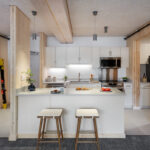
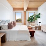
- Mass timber floor and roof panels are usually exposed on the ceiling side, providing an enhanced aesthetic not possible with other structural systems. From a development perspective, this can create market distinction and enhanced leasing velocity. Other benefits include a thinner structural system that can impact floor-to-floor heights, head heights, and overall building height; sustainability; speed of construction; and fewer installers required on site.
To keep up with the construction speed of mass timber floor panels, it is often beneficial to prefabricate/panelize the wood bearing walls off site.
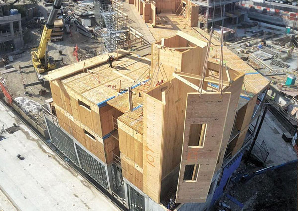
Mass Timber/Light-Frame Examples
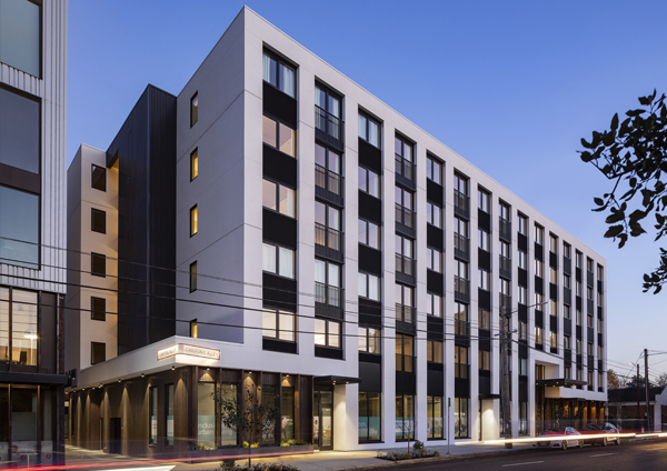
The Canyons | Portland, OR
- Four stories of cross-laminated timber (CLT) and light-frame wood over a two-story concrete podium
- Type III-A over Type I-A
- 110,000 SF
- 70 residential units (all ADA units; multi-generational housing)
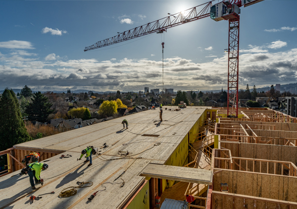
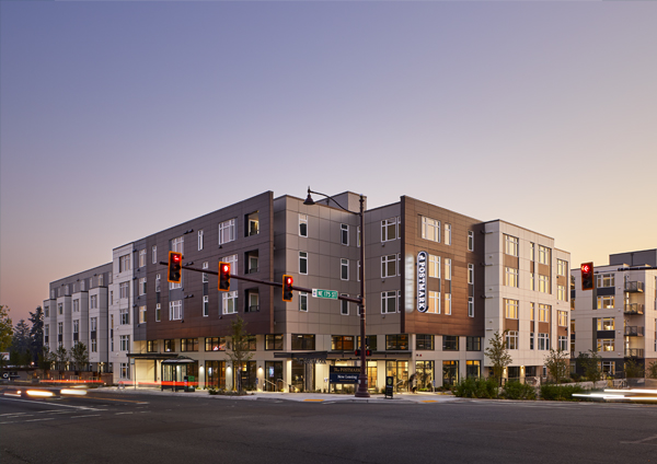
The Postmark Apartments | Shoreline, WA
- Two buildings, each with five stories of CLT and light-frame wood
- 333,560 SF; each 30,000 SF floor installed in three days
- 243 market-rate apartments
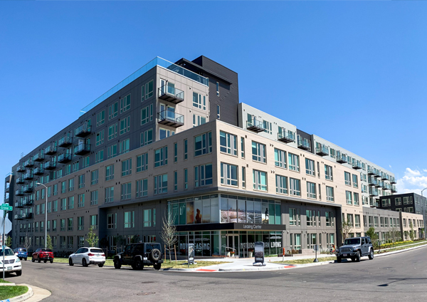
Cirrus | Denver, CO
- Five stories of CLT and light-frame wood over a two-story concrete podium
- Type III-A over Type I-A
- 230,000 SF
- 292 residential units
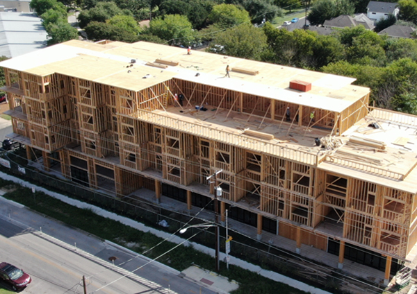
The Duke | Austin, TX
- Three stories of CLT and light-frame wood over a one-story concrete podium
- Type V-A over Type IV
- 44,000 SF
- 34 luxury apartments over ground-level retail
Railyard Flats | Sioux Falls, SD
- Four stories of dowel-laminated timber (DLT) and light-frame wood; connecting two-story office building with DLT floor panels on glulam beams and columns
- Type V-A
- 62,000 SF
- 41 loft-style apartments over ground-floor retail and two stories of office space
Junction Lofts | West Des Moines, IA
- Three stories of CLT made from structural composite lumber and light-frame wood
- Type V-B
- 16,000 square feet
- Residential; affordable housing for households earning 30-80% of the area median income (AMI)
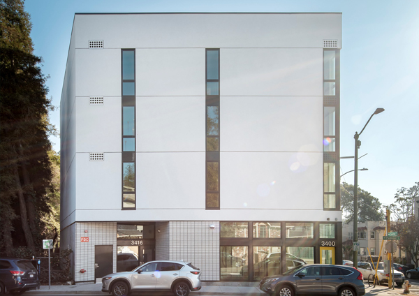
Project One | Oakland, CA
- Four stories of CLT made from structural composite lumber (SCL) and light-frame wood
- Type III-A
- 17,000 SF
- Nine market-rate apartments over ground-floor retail; each floor consists of 19 mass timber floor panels installed in three hours
Hotel Magdalena | Austin, TX
- Three buildings (one four-story, one three-story and one two-story) with DLT panels on light-frame wood bearing walls; DLT was also used for the elevator and stair shaft walls
- Type V-A over 1-A
- 73,735 SF
- 89 hotels rooms
Construction Types and Fire-Resistance Ratings
Mass timber floors and roofs on light-frame wood bearing walls are permitted in Types III-A, III-B, IV-HT, V-A and V-B construction. The specific material provisions in the 2021 IBC are as follows:
Type III (Section 602.3) – Mass timber and light-frame wood elements can be used in floors, roofs, and interior walls. Exterior walls can be constructed of noncombustible materials or, if the walls are required to have a fire-resistance rating (FRR) of 2 hours or less, fire-retardant-treated wood (FRTW).
Type V (Section 602.5) – Mass timber and light-frame wood elements can be used throughout the structure, including floors, roofs, and both interior and exterior walls.
Type IV (Section 602.4) – Mass timber elements meeting the minimum sizes in IBC Section 2304.11 can be used throughout the structure, including floors, roofs, and interior and exterior walls. Because this construction type is based in part on the inherent and long-demonstrated fire resistance of large solid wood framing, light-frame wood materials (e.g., 2x wall framing and wood structural panels) are generally prohibited. However, there are two exceptions to this, both of which are applicable to this hybrid style of construction. Type IV-HT permits the use of light-frame wood wall materials for:
- Exterior wall framing when the materials are FRTW and the required rating of the exterior walls is 2 hours or less
- Interior partitions when the wall has a minimum FRR of 1-hour per Section 2304.11.2.2
This hybrid style of construction is limited to five stories of wood framing and an overall building height of 85 feet (in Types III-A and IV-HT) for residential occupancies. Although the 2021 IBC introduced three new construction types—IV-A, IV-B and IV-C—which permit mass timber buildings up to 18 stories and 270 feet in height, these new construction types require mass timber or non-combustible materials throughout. The use of light-frame wood is not permitted.
Once the construction type has been selected, the FRR of structural elements will be dictated by IBC Table 601. For multi-family occupancies, additional FRR requirements for elements such as walls and floors separating dwelling units and corridor walls are specified elsewhere, such as IBC Sections 420, 708, 711, and 1020. In most cases, the FRRs in Table 601 will be as or more restrictive than the requirements in other sections. However, a few notable exceptions are corridor walls, unit separation walls, and floor assemblies that separate dwelling units in Types III-B and V-B projects. Table 601 would indicate a 0-hour FRR requirement, but other sections of the code indicate a minimum 1/2-hour FRR.
Light-frame wood wall assemblies in Types III, IV-HT and V construction typically require a 1-hour FRR, though 2 hours is required for some exterior walls. This has been the case for years and there are many tested assembly options available. Unit demising walls and corridor walls will typically take one of three forms:
1. Single stud wall with resilient channels (e.g., UL U327 and GA WP 3241)
2. Staggered stud wall (e.g., GA WP 3910)
3. Double stud wall (e.g., GA WP 3820)
Both faces of a wood stud wall assembly will be covered with one or two layers of Type X gypsum wallboard.
Lateral System Options
When taking this hybrid approach, most design teams will look to utilize the interior and exterior light-frame walls as shear walls. The nuances of wood stud shear wall design in typical mid-rise multi-family projects (e.g., lack of solid exterior walls, the need to assess flexible vs. semi-rigid vs. rigid diaphragms) also apply to these hybrid solutions. Wind and seismic design forces for the shear walls as well as the mass timber diaphragms can be obtained from ASCE 7, and design values from the American Wood Council’s Special Design Provisions for Wind and Seismic (SDPWS). The 2021 SDPWS was the first version to include narrative on the design of CLT diaphragms. For additional information on the design of CLT diaphragms, see WoodWorks’ CLT Diaphragm Design Guide. Floor diaphragms composed of other mass timber materials, such as nail-laminated timber (NLT), dowel-laminated timber (DLT) or glue-laminated timber (GLT), are typically covered with wood structural sheathing, with this sheathing used as the blocked diaphragm per SDPWS requirements.
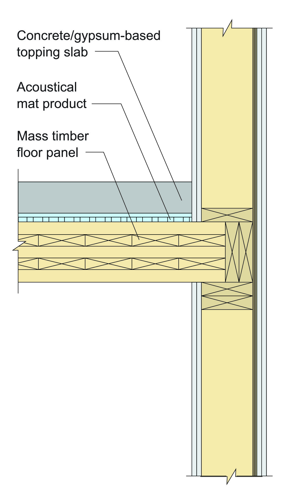
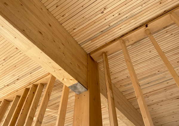
Figure 1 – Typical hybrid floor-to-exterior wall structural detail
Acoustic Design Considerations
Acoustic performance is a critical design criteria in multi-family buildings, more than perhaps any other building type. However, acoustics are also just one aspect of building performance and must be considered in combination with other requirements such as fire protection and structural systems. To determine an optimal design solution, it is important to understand how the design and detailing for each individual system affects the others—especially when using a newer system such as a mass timber floor assembly. Developing an understanding of required acoustical performance with the owner is another best practice that should not be overlooked. While there are code minimums for acoustics, some owners will aim for performance levels beyond code minimums as shown in Table 1.
Table 1 – Acoustical isolation between units – airborne (STC) and impact (IIC)
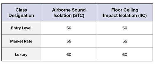
IBC Section 1206 lists requirements for acoustical performance of walls, partitions, and floor/ceiling assemblies in multi-family buildings. These assemblies, which separate one dwelling unit from another or from public areas, must have a sound transmission class (STC) rating of 50 and, in the case of floor/ ceiling assemblies, an impact insulation class (IIC) rating of 50. (These ratings can be reduced to 45 when field tested.) STC measures how effectively a wall or floor/ceiling assembly isolates airborne sound and reduces the level that passes from one side to the other. Examples of airborne sound include conversation and music. IIC measures how effectively a floor/ceiling assembly blocks impact sound from passing through a floor/ceiling and only applies to those assemblies. Examples of impact sound include foot falls and a book dropping on the floor.
Designing Mass Timber Floor Panels for Acoustic Performance
Since mass timber floor assemblies typically leave the panel exposed on the ceiling side, asymmetric assemblies are necessary. A bare 5-ply CLT floor panel has an STC of about 40 and an IIC of about 25, so to meet or exceed code minimums, additional mass, decouplers and/or noise barriers are added on top of the panels. A common floor build-up includes a mass timber panel, covered by an acoustic mat and then a poured concrete or gypsum-based topping, which is usually in the range of 1 to 3.5 inches thick. Considering the variables of mass timber panel types and thicknesses, acoustic mat types and thickness, topping density and thickness, and types of floor finish, this floor assembly can result in STC and IIC ratings up to the mid 50s. For additional information on the acoustical design of mass timber floor panels, see the WoodWorks publication, Acoustics in Mass Timber: Room-to-Room Noise Control. For information on mass timber assemblies, including test results, see WoodWorks’ Inventory of Acoustically-Tested Mass Timber Assemblies.
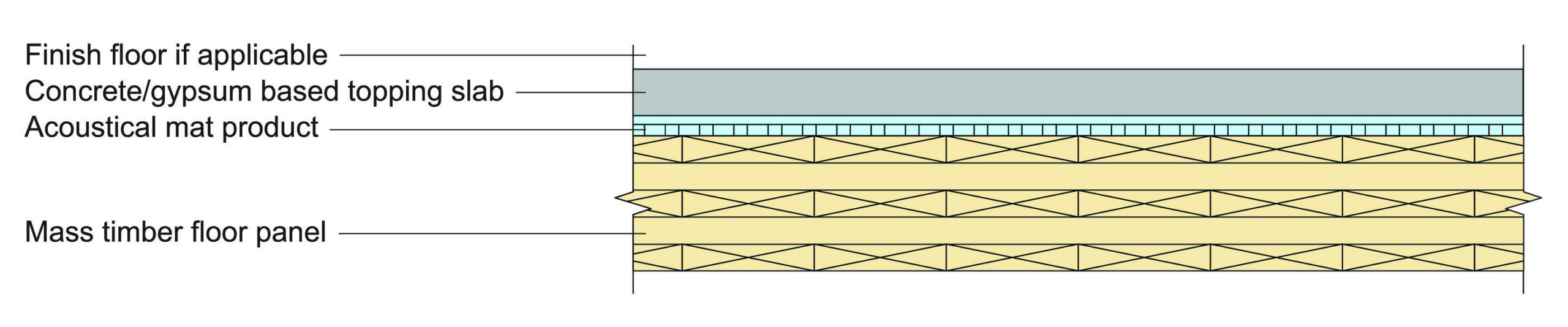
Figure 2 –Example mass timber floor assembly with topping and acoustic
Acoustic Design of Light-Frame Wood Wall Assemblies
Due to their long history of use, much is known about the acoustic performance of light-frame wood walls in multi-family buildings. In general, the three options for unit demising and corridor wood stud walls are single stud walls, staggered stud walls, and double stud walls.
To meet the minimum rating of STC 50, single stud walls usually require resilient channels on one side. Since unit demising walls usually need to accommodate hanging cabinets, shelves, televisions, etc., and since these hung elements would likely negate much of the acoustical benefit of resilient channels, this wall type is not commonly used for unit demising walls. Similar concerns exist for corridor walls, though resilient channels could be installed on the corridor side of the walls.
To meet the minimum rating of STC 50, single stud walls usually require resilient channels on one side. Since unit demising walls usually need to accommodate hanging cabinets, shelves, televisions, etc., and since these hung elements would likely negate much of the acoustical benefit of resilient channels, this wall type is not commonly used for unit demising walls. Similar concerns exist for corridor walls, though resilient channels could be installed on the corridor side of the walls.
Single stud wall with resilient channels on corridor side of wall / Photo WoodWorks
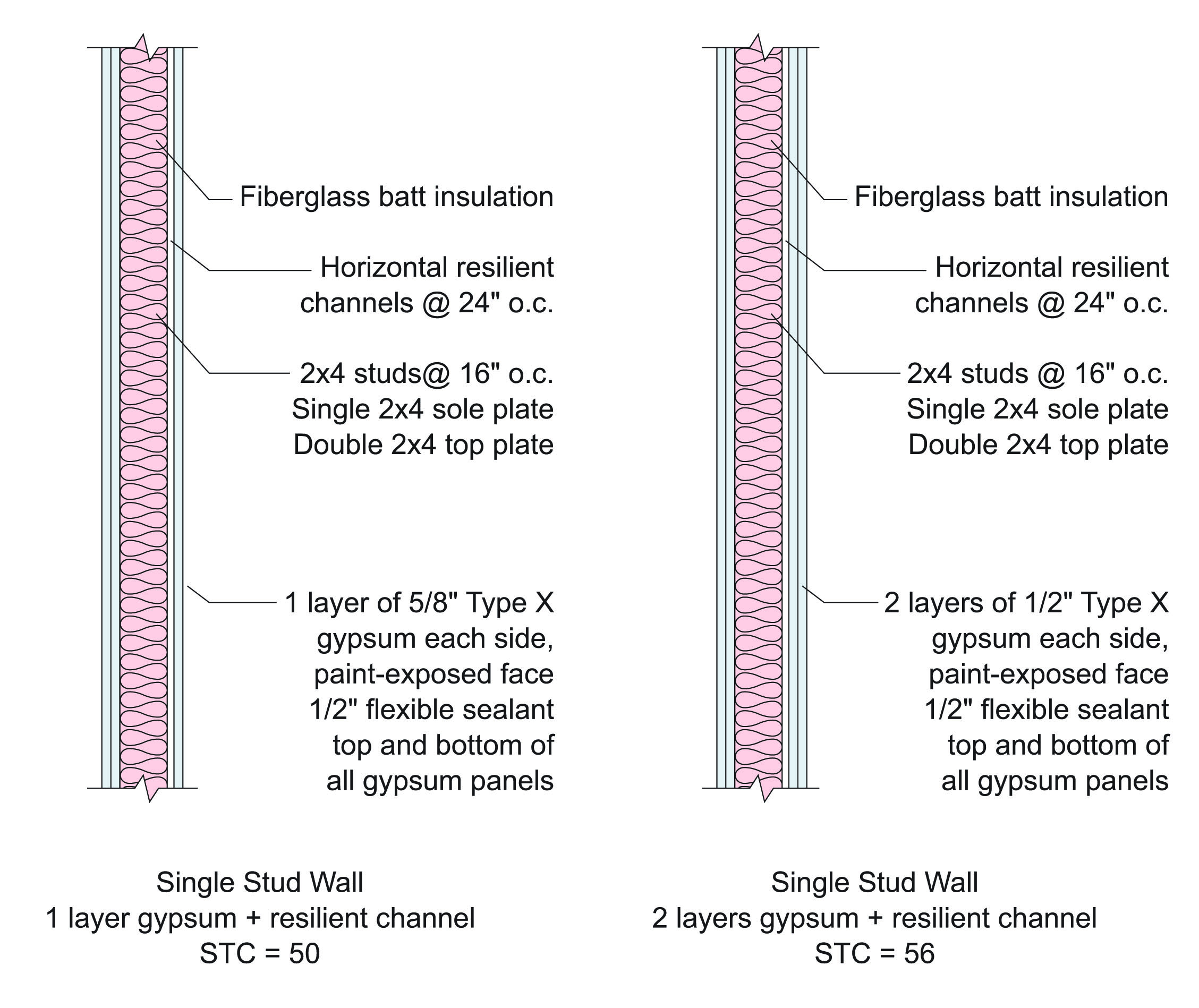
Figure 3 – Options for single stud walls with resilient channels and STC of 50+
Staggered stud walls are an option for achieving STC 50 without resilient channels. The typical construction of this style of wall includes 2×6 top and bottom plates with 2×4 studs alternating on each side of the plates, with each row of studs at 16″ or 24″ o.c.
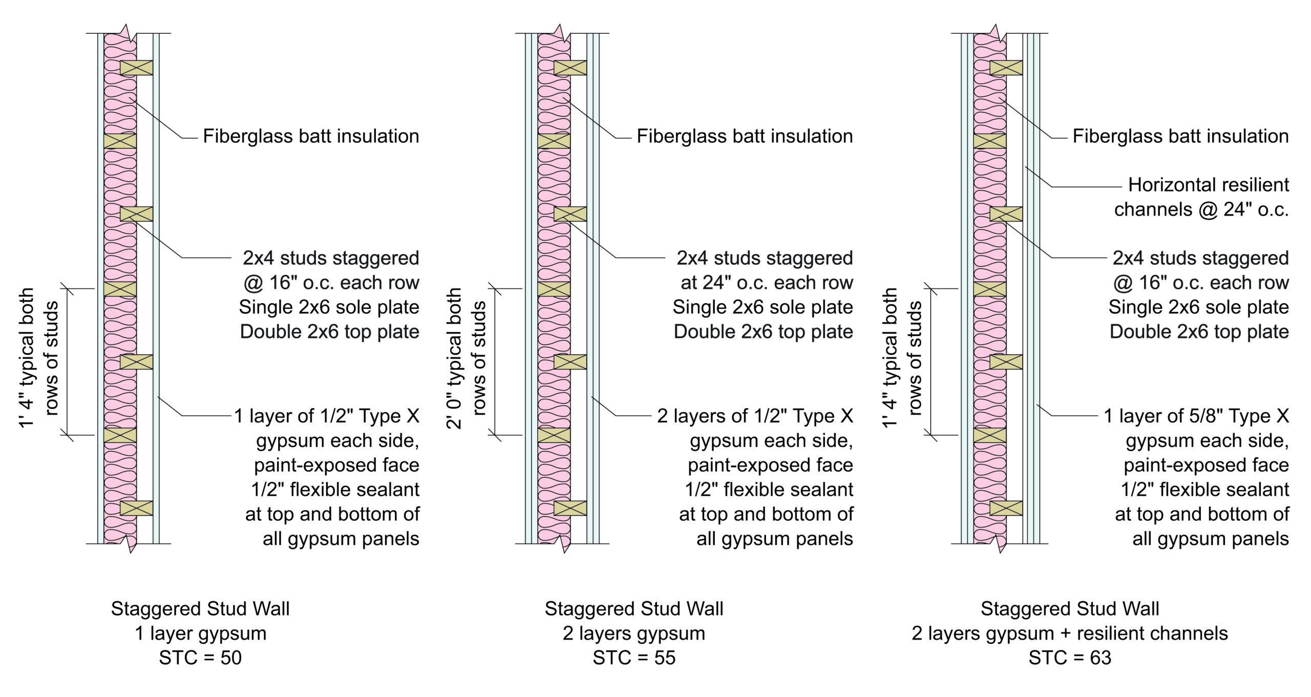
Figure 4 – Options for staggered stud walls with and without resilient channels and STC 50+
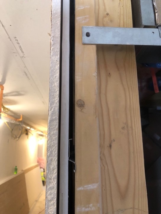
When using a staggered stud wall assembly, it is common to add a layer of wood structural panels (WSPs) to one side of unit demising walls and corridor walls when using them as shear walls. To maximize their capacity and stiffness in this application, a common framing member such as wood blocking is placed between studs to tie adjacent WSPs together. However, proper installation of the blocking is crucial; having the wood blocking come in contact with both rows would negate the acoustical benefit of isolating the two rows of wood studs. The photo below shows a common but inadvisable condition where the wood blocking is creating a short circuit for noise transfer. In lieu of this condition, it is preferable to rotate the wood blocking so its wide face is in contact with the back side of the WSP, but doesn’t come in contact with the opposite row of studs. For more information, see the WoodWorks articles, Requirements for Shear Wall Blocking at Panel Edges and Impact of Wall Stud Size and Spacing on Fire and Acoustic Performance.
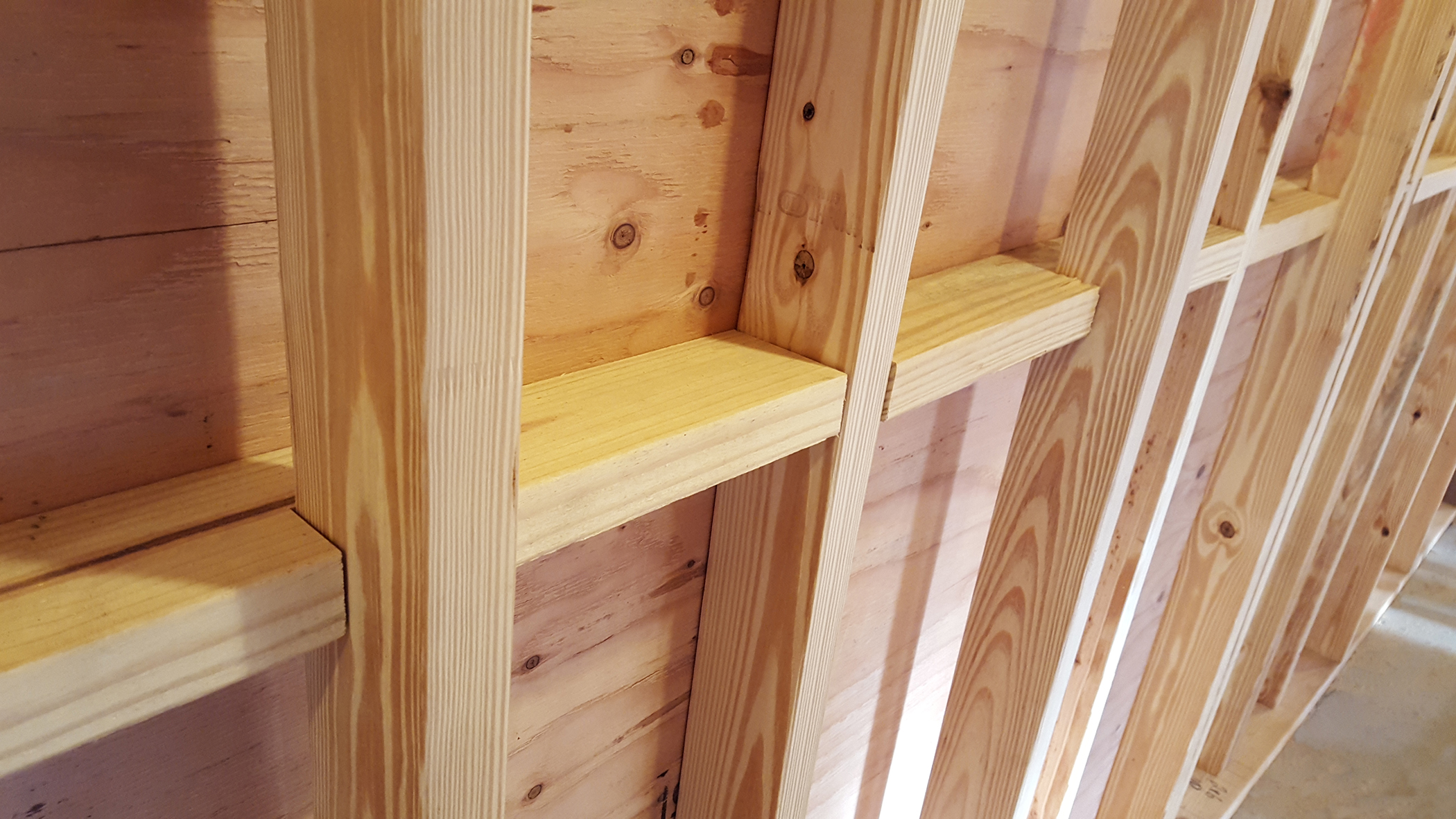
Staggered stud wall with shear wall blocking in contact with both rows of studs, causing sound transfer touch point / Photo WoodWorks
The most robust interior wall for multi-family applications is the double wall, though it’s also among the most expensive and takes up the most useable space. By leveraging two separate walls, each with their own wall plates and an air gap between them, the benefits of acoustical isolation are maximized. As shown below, a double stud wall assembly can achieve STC 60 or greater without the use of resilient channels.
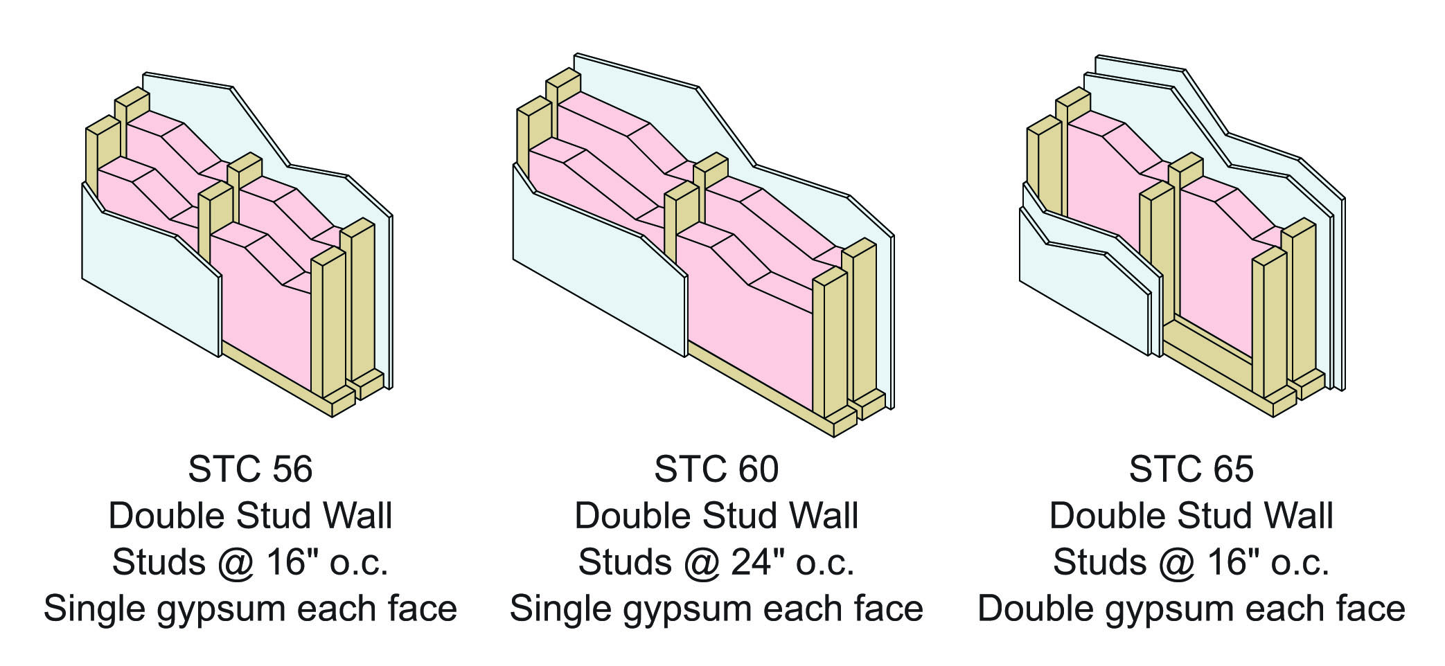
Figure 5 – Options for double stud walls with STC 55+
As with staggered stud walls, WSPs may be added to double stud walls to improve their performance. In this scenario, WSPs should be placed on the outside face of the studs and not in the air cavity between the stud rows. Placing WSPs between walls reduces the depth of the air cavity and can create trapped air spaces, which increases the risk of the walls coupling together. When added between the walls, WSPs can also create resonance of the two thinner wall systems. In this case, the walls radiate at the same frequency, coupling with each other, which reduces the wall system’s acoustical effectiveness. WSPs placed on the outer faces of the walls should maintain a depth of air space that corresponds with the tested assembly performance. Figure 6 illustrates the acoustical effect of sheathing placement in double wall assemblies. For more information, see the WoodWorks article, Adding Wood Structural Panels to Acoustically-Tested Assemblies.
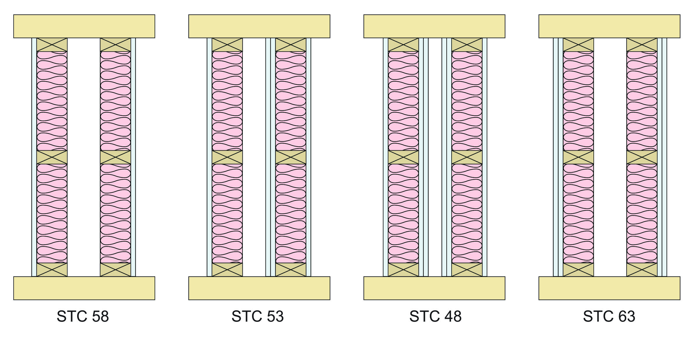
Figure 6 – Acoustical impact of sheathing placement in double stud wall
In addition to selecting the proper floor and wall assemblies, it is important to consider the details used at the intersection of two assemblies. One approach is to isolate the topping slab as shown in Figure 7. Another option is to break each mass timber floor panel over each unit demising wall to create acoustic isolation and prevent sound from travelling between units by way of a continuous panel, as shown in Figure 8.
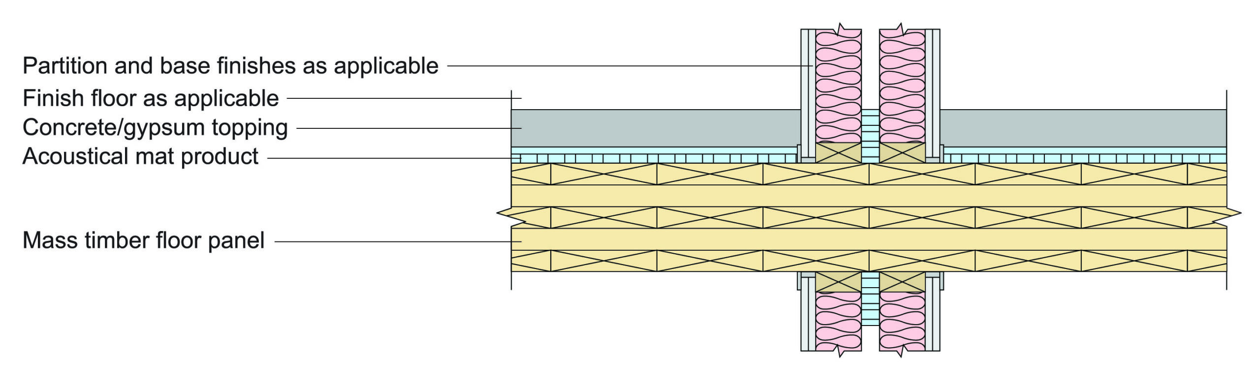
Figure 7 – CLT floor panel at unit demising
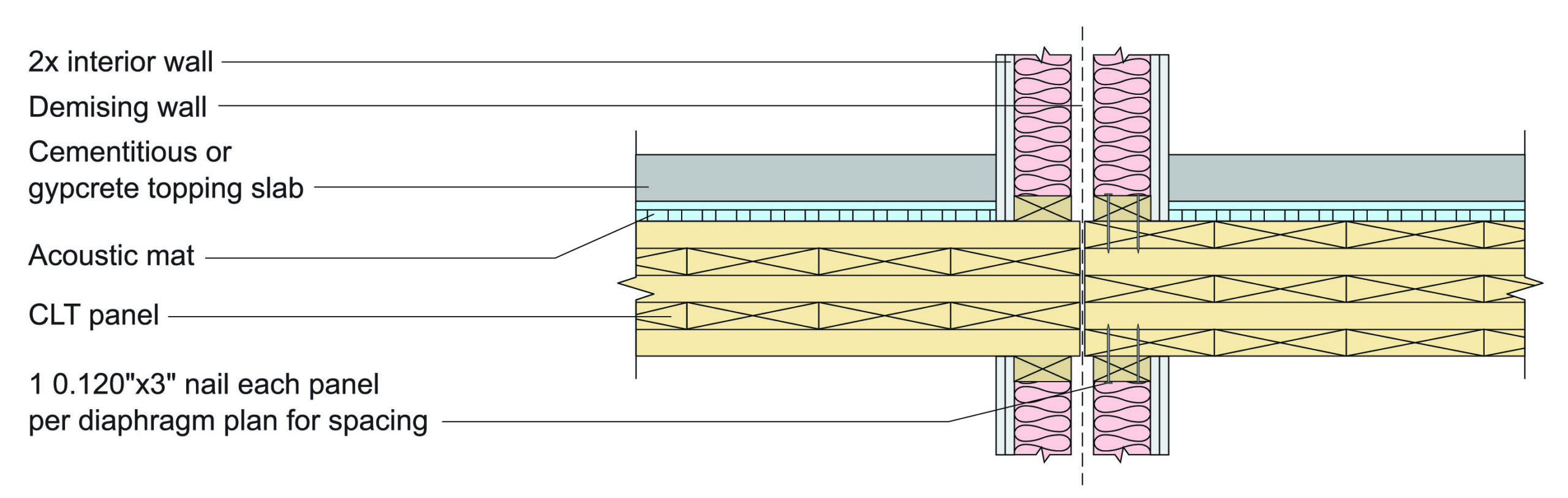
Figure 8 – Isolated mass timber floor panels at intersection of floor and wall assemblies
For examples of mass timber floor to light wood frame wall intersection details, see the WoodWorks publication Index of Mass Timber Connections.