Expert Tips
The Modular Enclosure: Protect Your Investment During Every Phase
How traditional building enclosure design considerations translate to modular projects
The building enclosure includes any part of a building that physically separates conditioned and unconditioned spaces. For both modular and traditional site-built construction, the final building enclosure is generally the true exterior of the building. However, a unique consideration of modular construction is that each module often needs its own protective layer during storage, transportation, and installation. Modules may also include other factory-installed components like insulation and cladding systems. The topics in this article represent some of the greatest challenges and benefits of modular construction, including how the protective layer functions during pre-site construction phases and how this layer, and other prefabricated enclosure layers/systems, may become part of the final building enclosure.
Building Enclosure Control Layer Overview
The building enclosure is subject to environmental loads such as liquid water and water vapor, air, and heat in addition to other loads like fire and sound. Figure 1 shows how the enclosure generally manages these loads using a system of control layers, including stand-alone materials or systems designed to manage specific loads. In general, each control layer (except possibly vapor control) needs to be identifiable and continuous at each assembly. Each layer also needs to be detailed to perform as intended throughout the lifespan of the building.
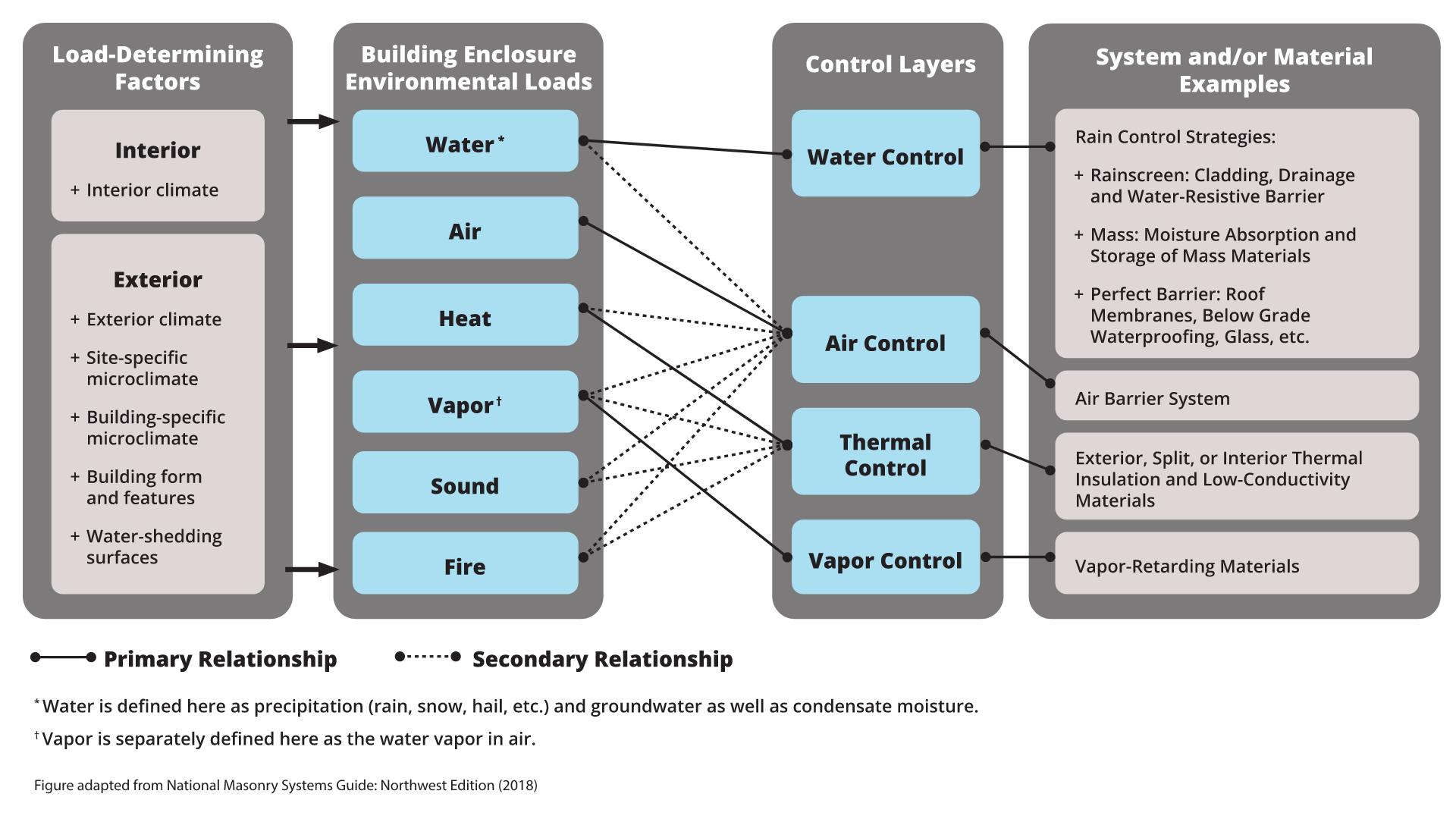
Figure 1 – Building enclosure loads and the associated control layers
The design and construction team can use the control layer concept to understand the role and importance of each enclosure system and/or material. The team can also use this concept to evaluate the building enclosure assemblies and details; in traditional construction, this often includes identifying missing, discontinuous (if required to be continuous), or inappropriately redundant control layers. This concept is also instrumental in modular construction to:
- Identify continuity of the (sometimes temporary) protective layers that may be responsible for managing water exposure during pre-site construction stages.
- Detail module-to-module joints of the final building enclosure to ensure control layer continuity.
- Limit gaps in the construction documents, including those for factory or on-site installation.
- Reduce excessive materials and related costs.
Moisture Control
Modular construction presents unique moisture (both water and water vapor) control challenges not typically encountered in conventional site-built construction. A few challenges arise from the fact that finished interior work is typically completed in the factory and transported within the modules to the jobsite, unlike traditional site-built construction where the building is weathered-in before installation of interior finishes. As a result, the modules—including their structural system and any sheathing, insulation layers, and interior finishes—are susceptible to moisture exposure during the project’s storage, shipping, and construction stages. Any moisture damage to the modules can be significantly more challenging to repair, risking the removal of adjacent finished work and costly schedule impacts.
Resilient Design for Water Control
Modular buildings with a resilient moisture control design can help reduce the risk of moisture-related damage. A resilient design limits the exposure of module components and water entry into a module once it’s left the controlled environment of the manufacturing facility and until the final enclosure is installed.
The basis of a water-resilient design begins by protecting all six sides of the module (see Figure 2) in the factory before transporting or storing the module outdoors, where it may be exposed to weather. The design essentially provides each module with its own water control layer for protection during the storage, transportation, and erection phases of modular construction. While this design may require covering more surface area of the building with roof and water-resistive barrier (WRB) membrane materials than standard site-built construction, it is necessary to mitigate the risk of damage to moisture-sensitive interior finishes.
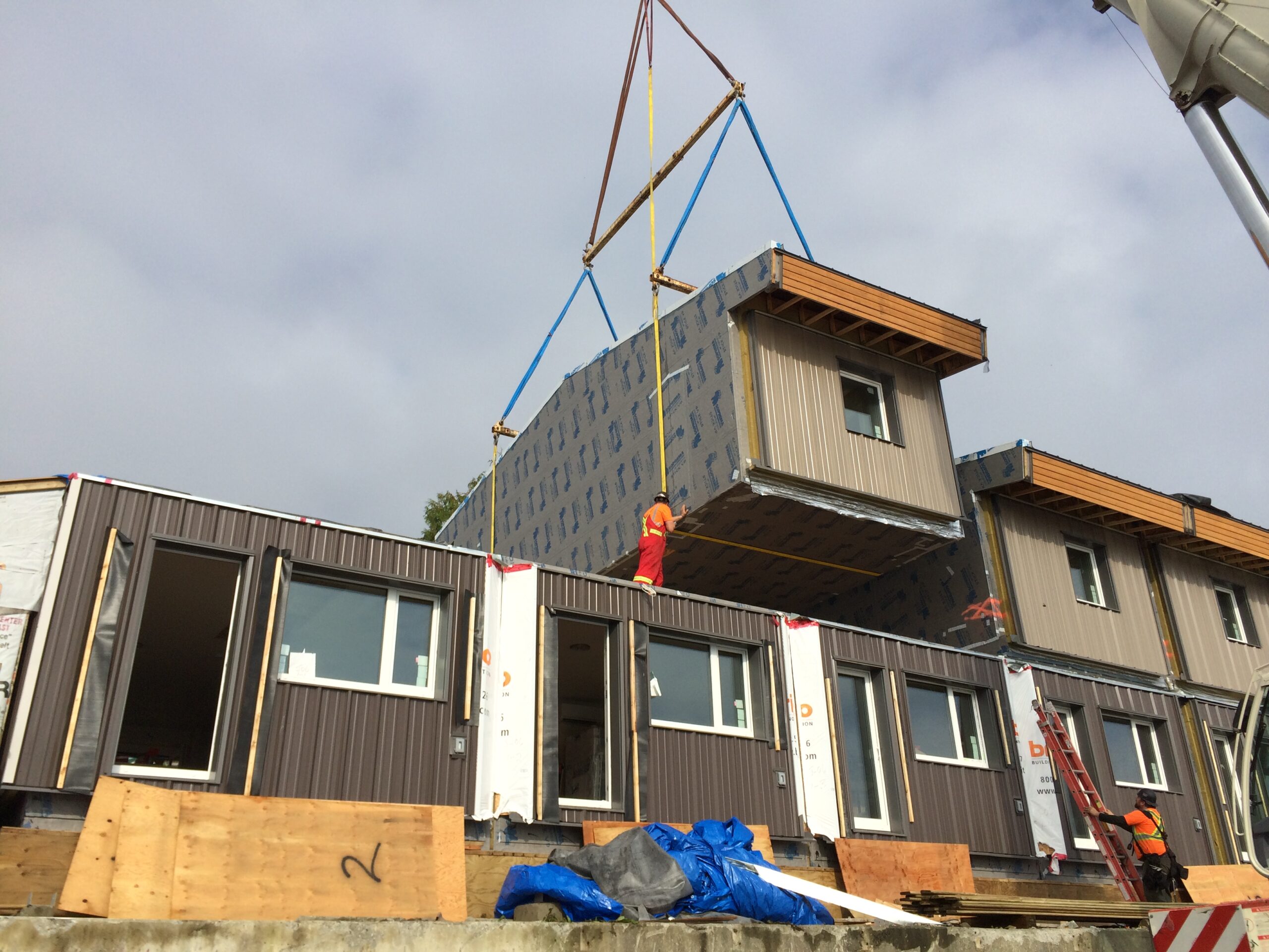
Figure 2 – A module wrapped on all six sides is placed during on-site construction.
The water control layer selected to cover each side of the module depends greatly on climatic factors and the project’s risk tolerance. Depending on the project location and seasonal weather patterns, the modules may have a high risk of becoming wet during transportation and storage. This is especially true if they are transported over a large distance, over water, through differing climate zones, and during rainy or snowy conditions. Protecting the modules from wetting during transportation, storage, and even construction can improve the chance that the modules will be dry when they are craned in place. To protect each side of the modules, consider the following practices:
- Topside of modules: Horizontal surfaces are particularly vulnerable to moisture. No matter the climatic factors or risk tolerance, it is best practice to protect the topside of modules with a fully adhered roof membrane product. This applies to all modules, whether the module forms the final roof enclosure or is concealed entirely within the final building enclosure. It is often sufficient for this roof membrane material to be the same vapor barrier/temporary roof membrane product used on conventional low-slope roof applications.
- Vertical sides of modules: A fully-adhered WRB membrane over sheathing on the exterior walls of all modules is a durable and water-resistant approach. While some module walls may not form the final enclosure, using a fully-adhered WRB, such as a self-adhered or liquid-applied membrane, can limit water migration (and related damage) behind the membrane in the event of damage and moisture exposure.
- Underside of modules: It is a best practice to provide a fully-adhered WRB on the underside of all modules. The bottom of a module may seem less vulnerable; however, it is prone to damage and moisture exposure from gravel, debris, and splashback during ground transport and storage on site.
While fully-adhered membranes provide the most durable water control layer on the vertical sides and underside of each module, mechanically attached WRBs perform better than relying on polyethylene shrink wraps. In drier climates, polyethylene shrink wraps are sometimes used as the only water control layer for modules during the storage, transportation, and erection phases of the project. These products are usually thin and easily damaged, and small holes in the shrink wrap can lead to water leaks and potentially cause damage to modular units when left unmitigated.
Additional Moisture Considerations
So far, this article has focused on external water sources but moisture contained within a module due to fabrication (e.g., finish installation activities) also needs to be considered. Where appropriate, providing a vapor-permeable WRB membrane on the interior walls can allow some drying of built-in moisture. However, additional measures beyond increasing the vapor permeance of the water control layer may need to be considered if there is a risk of trapping excessive moisture within a module for an extended period of time.
The vapor permeance of the module’s water control layer also needs to be considered within the greater context of the final building use and assemblies. A module’s water control layer may form part of the final building enclosure; as such, it needs to be appropriately selected for long-term performance. A water control layer may also be contained within the building and should be confirmed for appropriateness when dividing spaces of different uses and conditioning.
Moisture Management Best Practices
- Protect all six sides and “dry-in” each module in the controlled factory setting before transporting or storing the modules outdoors where they can be exposed to moisture.
- Install a fully-adhered roof-grade membrane on the top side of each module, whether it will be a final roof module or not.
- Install a self-adhered or fluid-applied WRB on the four exterior vertical sides and underside of each module. It is a best practice for this WRB to be vapor permeable, if appropriate based on the final building design needs.
Detailing for Control Layer Continuity
Modular construction is a unique combination of fast-paced premanufacturing of building components and on-site assembly, including final detailing of the building enclosure. The factory versus on-site installation scopes are determined during the design phase and account for both pre-construction protection and the final enclosure.
Optimizing the enclosure design of a modular building often means that water control membranes serve a dual purpose—protecting modules during pre-construction phases and as the water control (and possibly air control) membrane for the final building enclosure. Modules may even be pre-fabricated with insulation and cladding layers that are final components. As a result, once modules are erected, critical module-to-module tie-ins need to be completed to create continuity of all control layers including finish cladding systems. Figure 3 and Figure 4 provide schematic examples of module-to-module joint detailing where the continuity of layers is achieved.
These details show the exterior joints between modules infilled (on site) with a final WRB and air barrier membrane (water and air control), exterior insulation (thermal control), and cladding layers to maintain the continuity of the final building enclosure control layers.
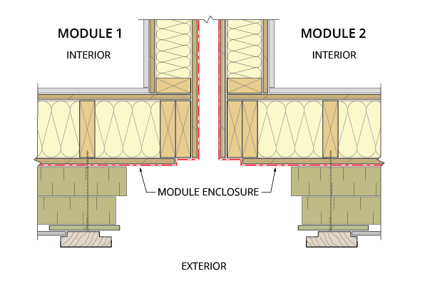
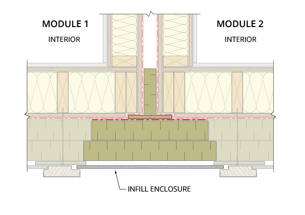
Figure 3 – Plan detail of a wall-to-wall joint directly after erecting (left) and after the final enclosure is complete (right)
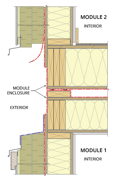
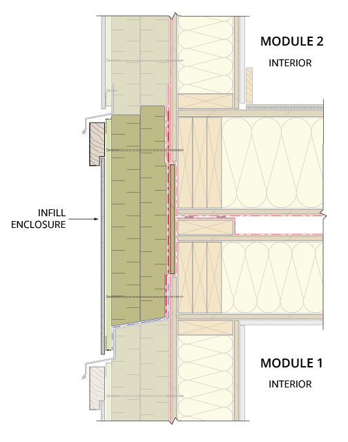
Figure 4 – Cross-section progress detail at a floor-to-ceiling connection beginning with the top of one module (left), the addition of a module above (middle), and site installation to establish continuity of the control layers (right)
If a self-adhered WRB is used, the project team will need to carefully plan the sequencing of its installation in the factory so the underside of the modules can be covered while also leaving a tail of unadhered WRB for future tie-in with the infilled WRB installed on site (see 4). As with traditional site-built construction, it is a best practice to provide positive shingle-lapped joints between sheets of WRB and air barrier membranes. During design, the project team should carefully plan similar details for module tie-ins with the roof units, site-constructed foundation piles, crawlspaces, and atypical module-to-module joints. The interfaces between site build conditions such as the foundation and factory built details should be carefully considered to accommodate tolerances and structural attachment methods and how these will influence the control layer continuity.
Other factors to consider when detailing module-to-module connections include:
- Modules may be slightly misaligned once lifted into place due to construction tolerances. Misalignment and its consequences can be minimized by coordinating sufficient factory and field tolerances and choosing materials and cladding systems that can accommodate misalignment when it happens.
- Modules are often required to have temporary structural supports to protect them while being craned/lifted into place. These supports penetrate each module water control layer and may penetrate final enclosure layers, creating pathways for water intrusion during site work or even in service if not appropriately sealed. It is a best practice to develop details that show how temporary structural supports are sealed once removed.
Detailing Best Practices
- Finalize all details before modular construction begins at the factory. Account for factory scope versus on-site scope and the installation sequence of field installation transitions from the beginning of the project.
- Develop details that demonstrate how the building’s final water, air, thermal, and vapor control layers are made continuous at module-to-module joints, at interfaces with site-built construction such as foundation walls, and in crawlspaces.
- Account for factory and field tolerances and choose materials that can accommodate misalignment.
- Provide details to show how temporary structural supports will be removed and sealed on each module.
Transport and Construction Phase Water Management
Depending on location and seasonal weather patterns, a project may be at high risk of module wetting during the transportation, storage, and erection stages. Although modules may already be receiving a protective layer to reduce water exposure on all six sides, the project team can increase the likelihood that modules are dry when craned into place by following these additional steps:
- Minimize membrane damage. If modules must be transported over a large distance or by barge over water, consider using permanent, self-adhered, or liquid-applied membranes instead of non-adhered, temporary protection. High-speed travel (ground transport) can induce driving rain conditions and cause damage to loose membranes, such as mechanically attached wraps. If a permanent self-adhered or liquid-applied membrane is damaged in one area, exposure to water is generally limited to the area of damage. The adhered nature of these products minimizes the opportunity for water to travel further between the membrane and sheathing.
- Protect membranes from abrasion. Tie-down straps and other connections can wear on protective membranes during transport. Protect modules with a membrane that will remain tight to the substrate to avoid abrasion. During long-distance road travel, daily inspections and patching can ensure the temporary protection remains intact; because modules are often oversize loads, it is not uncommon for adjacent materials like tree branches to cause damage. Clean all road and construction debris like sawdust from the modules before placement. Additional membranes, such as those at joint connections, typically cannot be installed over such debris.
- Develop a contingency plan. An adequate contingency plan accounts for weather events during module shipping, on-site storage, and installation. This plan provides moisture management provisions, including removing water on surfaces and in cavities, and the complete drying (through heating, ventilation, or other means) of elements that get wet. The contingency plan may include additional temporary protection such as “night seals” applied at the end of each day’s work and protection of openings, pick points, and other vulnerable areas.
- Provide temporary protection. After the modules have been erected, moisture can accumulate in the interstitial spaces between units if joints have not been adequately sealed (Figure 5). Moisture accumulation can be difficult to observe and, unless discovered and remediated, may cause damage. This can be avoided by sealing horizontal module-to-module joints at each level and other areas at risk for moisture exposure and accumulation. Relying on tarps and plastic to temporarily waterproof the installed modules may be inadequate in heavy rain events. Inconspicuous holes in these tarps can cause damage to the interstitial spaces between units and to the interior finishes if no roofing membrane is installed beneath. Figure 6 shows an example of water pooled on temporary tarps over modules after each completed floor.
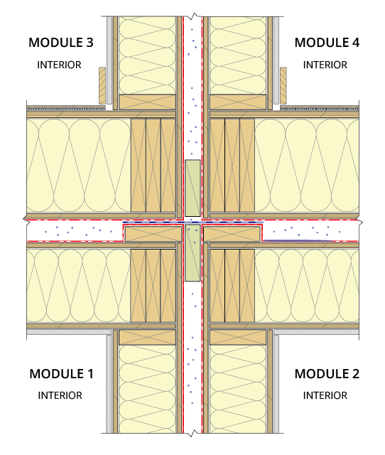
Figure 5 – Moisture trapped in the interstitial spaces between modules with limited ability to dry
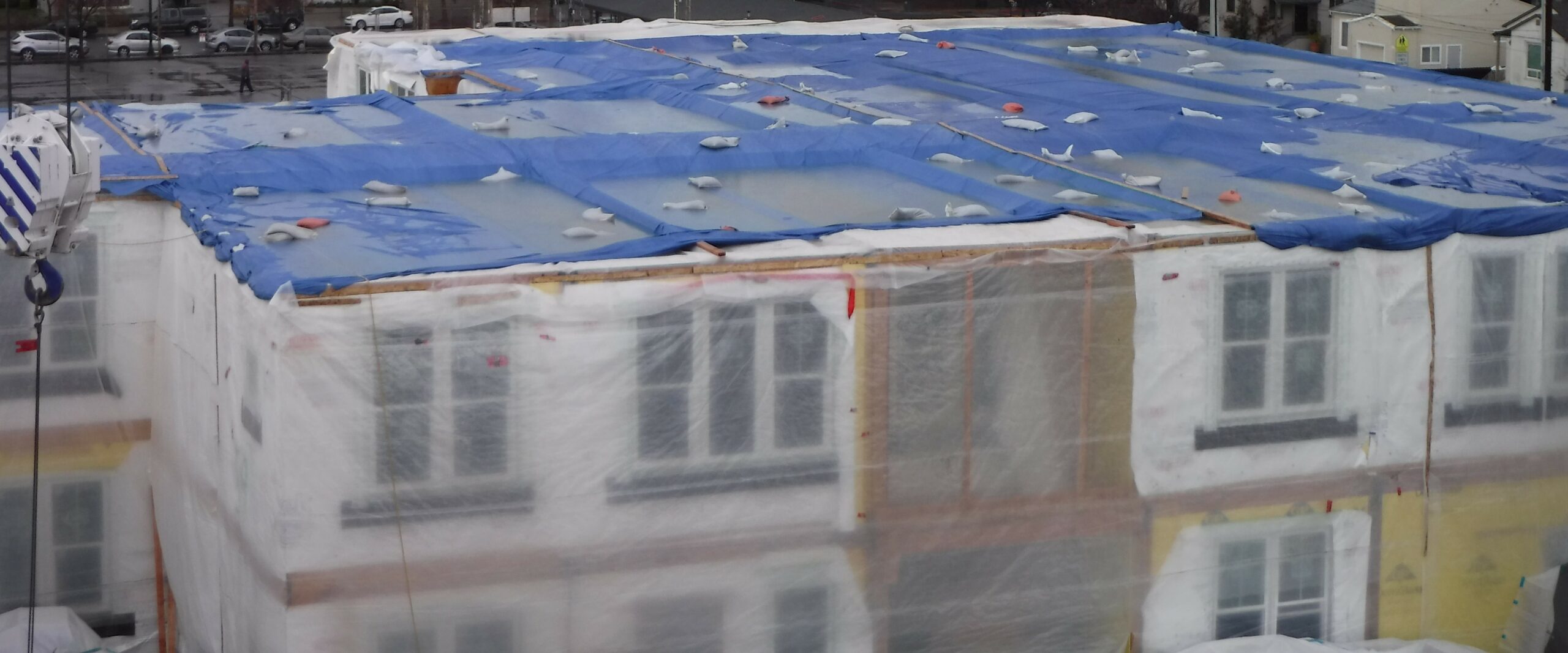
Figure 6 – Pooled water over tarps installed at intermediate module roofs
Temporary Transportation and Site Protection Best Practices
- Cover all six sides to protect each module in the controlled factory setting before transporting or storing the modules outdoors where they can be exposed to moisture. Use permanent, self-adhered, or liquid-applied membranes.
- Develop a contingency plan for weather events during module shipping, on-site storage, and erection.
- Monitor the continuity of protection layers throughout the construction phase; repair areas of damage after confirming the areas beneath are dry
- Seal horizontal module-to-module joints at each level and other areas at risk for moisture exposure and accumulation. Install a fully adhered roofing membrane over the horizontal joints on the top module after installation is complete.
- Seal any vertical module-to-module joints that may be exposed to wind driven rain. Depending on the level of exposure, a loosely laid or fully adhered membrane may be used.
Opportunities for Increased Energy Efficiency
The controlled environment of a manufacturing facility can make it easier to meet high-performance requirements (e.g., airtightness targets and exterior insulation continuity) than with traditional on-site construction of enclosure assemblies. The controlled environment is beneficial for consistent membrane application and detailing, especially when using exterior insulation, though site joints still need to be detailed well for module-to-module continuity. Attention to sealing these joints for air and water control is integral to meeting performance requirements. Figure 7 shows a module during the installation of exterior insulation in the factory.
Details can be designed to allow ease of installation for site-installed elements that cannot be included on the shipped module. Since the exterior WRB and air barrier often cannot be reliably sealed without leaving off large portions of cladding and membranes, it is generally simpler to design each unit to be individually airtight, including areas along the abutting walls and floors. This practice enables a mid-construction airtightness test in the factory and the repair of any details showing air leakage. The thermal, water-resistive, and cladding component tie-ins are then connected on site, and the continuation of the air barrier between modules is completed to ensure whole-building airtightness.
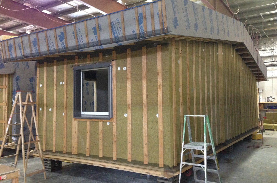
Figure 7 – Exterior insulation installed on a module in the factory
Case Study: Staff Housing Facility in Bella Bella, BC
In early 2015, the Vancouver Coastal Health Authority began seeking staff housing solutions for the remote community of Bella Bella, BC. The project team set out to build Canada’s first multi-unit modular Passive House facility (Figure 8). The rigorous Passive House standard aims to balance the climate conditions impacting the building with the daily needs of the building’s occupants to deliver a comfortable, healthy, and durable structure that uses minimal energy. By leveraging the advantages of modular design, the project team was able to meet the goals and overcome the challenges outlined in Table 1.
Using modular construction, the remote Bella Bella staff housing facility was completed in a timely manner while also achieving a high-performing building enclosure. Energy monitoring work has shown that the facility uses approximately 28.5 kBTU/ft2/yr (90 kWh/m2/yr) of energy with most energy consumed by internal loads (e.g., televisions and other plug loads).
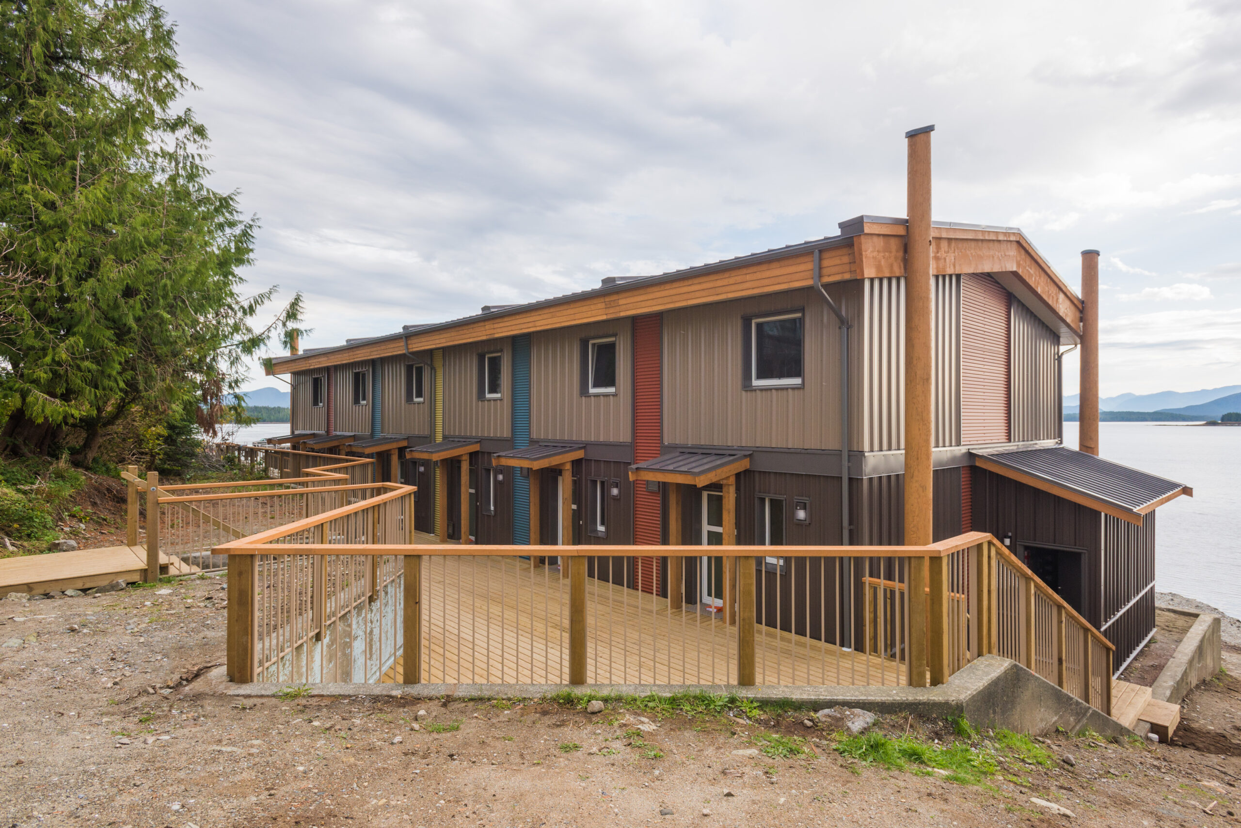
Figure 8 – Completed staff housing facility
Table 1 – Project goals and challenges for Vancouver Coastal Health Authority staff housing facility in Bella Bella, BC
Project Goals | Outcomes |
Fast Construction | |
The Vancouver Coastal Health Authority needed the building to be completed quickly so staff could move in as soon as possible. Modular construction was the optimal choice for the short timeframe. |
|
Passive House Certification | |
The project aimed to achieve the high-performance Passive House standard by September 2015. To achieve this goal, the building needed to meet strict criteria, including space heat demand, primary energy demand, and air tightness testing targets. The building could not exceed 0.6 air changes per hour (ACH) at a pressure of 50 pascals (0.6 ACH50) Due to the high-performance target, the project needed mid-construction airtightness testing to identify issues early on and allow repairs to be done before the building was clad. |
|
Project Challenges | Solutions |
Remote Location | |
The remote, rural location of Bella Bella had limited access to trades and materials. The project site had beach access but no easy trucking access. |
|
Wet Weather | |
Bella Bella experiences some of the wettest weather conditions in BC. The project needed robust moisture protection, not only for the final building but also for the individual modules during the transportation and erection phases. |
|
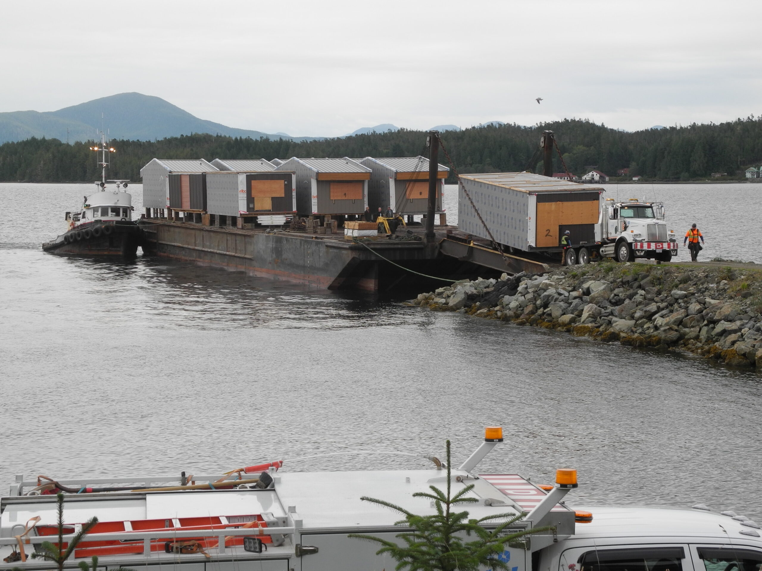
Figure 9 – Modules shipped by barge to the remote community of Bella Bella, BC
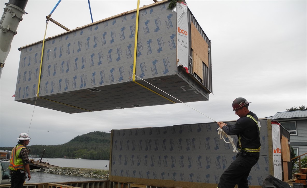
Figure 10 – Module being placed during installation
Related Resources
Finch, G. & Henderson, E. RDH Building Science Inc. (2020). Going Modular: Lessons Learned from High-Performance Affordable Housing.
Harrell, T. RDH Building Science Inc. (2016). Building Enclosure Design for Modular Construction.
Henderson, E. RDH Building Science Inc. Modular Construction for Energy Efficient, Affordable Housing in Canada.
Pinon, J. RDH Building Science Inc. Building Enclosure Design for Modular Construction.
Contributed by Bailey Brown, Matthew Bowman, and Denali Jones of RDH Building Science Inc.