Expert Tips
Panelized Wood Roofs: Enclosure Design for Long-Term Performance
Guidance for moisture risk management and thermal insulation placement in panelized wood roof assemblies across a range of climates and building uses
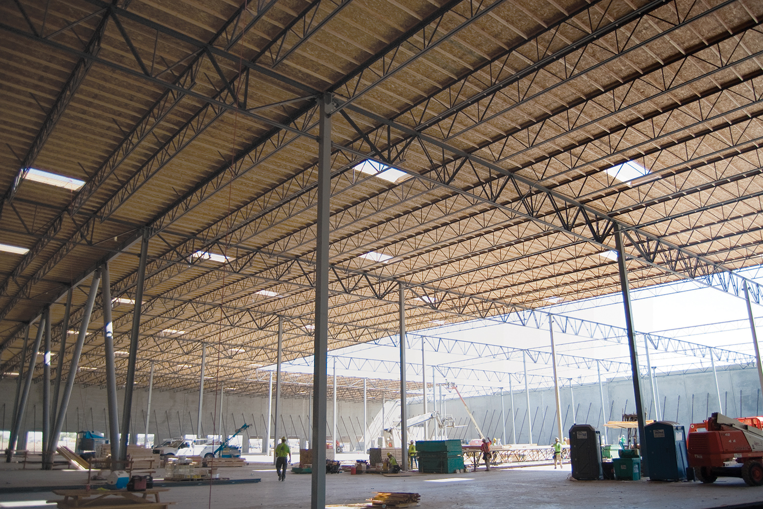
For an overview of panelized wood roof systems, including project typologies that lend themselves to wood construction, code considerations, structural and enclosure design, and assembly and installation, see the WoodWorks paper, Why Consider a Panelized Wood Roof System for Commercial Buildings. This article focuses on lightweight panelized wood roof systems; it does not address systems that use mass timber as a primary deck component.
This article references the 2024 International Building Code (IBC) and ANSI/ASHRAE/IES Standard 90.1-2025 (ASHRAE 90.1).
All roofs require coordinated water management, including positive drainage, durable roof membranes, compatible flashings, well-detailed penetrations, and clear maintenance access. They also need assembly components that support fire resistance and durability, such as an appropriate coverboard above insulation where required or recommended, and fastening and attachment details that account for wind uplift, membrane securement, perimeter conditions, and rooftop equipment loads. These practices do not replace climate- and use-specific roof design; they provide the foundation for reliable long-term performance. Understanding the location of thermal insulation and the air and water control layers is also critical to the long-term performance and durability of any roof, including a panelized wood roof system.
Control Layer Decisions That Drive Roof Performance
Early-stage design decisions determine the location of roof assembly layers that manage enclosure loads like rain, air pressure differences, heat transfer, and more. Layer-related decisions that drive long-term roof assembly performance include:
- Location of the water control layer – This layer is responsible for shedding rainwater and snowmelt and preventing water leaks.
- Location of the air control layer –This is the continuous layer that minimizes indoor and outdoor air transfer across the assembly. It may be the roof membrane, a separate layer applied to the deck, or a layer at the ceiling plane. Its location relative to the insulation can significantly affect assembly performance.
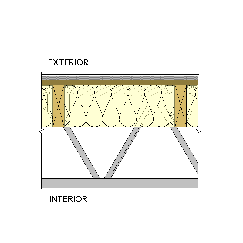
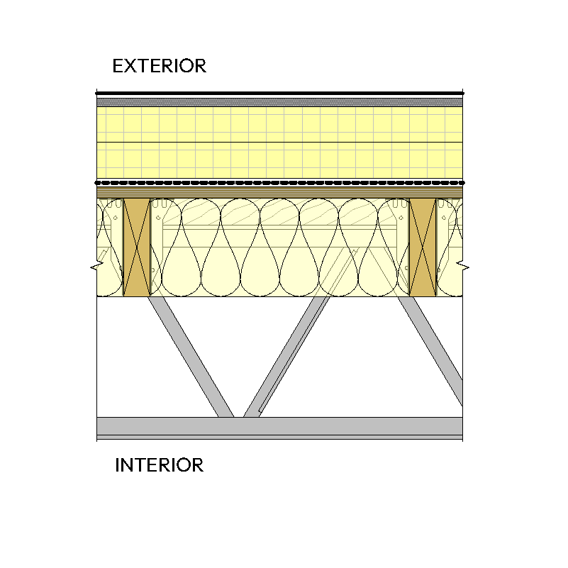
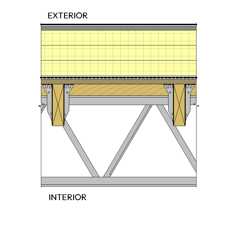
- Location of the thermal control layer – Thermal insulation may be entirely below the deck (between the sub-purlins), entirely above the deck, or split between the two.
Other choices, such as vapor retarders, ventilation, and more, follow from these primary decisions.
Table 1 illustrates three design strategies for panelized wood roof assemblies. The project-specific suitability of these strategies varies across climate zones, interior space uses, and conditioning needs.
TABLE 1: Hybrid panelized wood roof assembly with insulation a) between sub-purlins, b) between sub-purlins and above the roof deck, and c) above the roof deck. The amount of insulation shown in each assembly is representative. Roof slope is provided by the panelized wood roof structure and/or sloped insulation above the deck.
a) Insulation Below Deck | b) Split Insulation | c) Insulation Above Deck |
 |  |  |
Assembly Layers | ||
Exterior
Interior | Exterior
Interior | Exterior
Interior |
Discussion | ||
|
|
|
Energy Efficiency
Building energy codes, most commonly ASHRAE 90.1 and the International Energy Conservation Code (IECC), establish minimum insulation values and airtightness requirements for the roof assembly when specific interior space-conditioning thresholds are met. Required values vary by climate, space-conditioning category, and compliance path. The same building constructed in different climates is subject to different requirements, and the IECC reflects those differences.
Two insulation approaches predominate for panelized wood roofs as viewed through the code:
- Insulation entirely above the deck – Because the wood framing does not interrupt the insulation, the minimum R-value is lower. Common materials include high-density polyiso, mineral wool, and laminated insulation boards.
- Insulation below the deck or split across the deck (“attic and other” in the IECC) – This is typically batt insulation between sub-purlins, sometimes combined with a thinner layer of insulation above the wood deck. Compared to assemblies where insulation is located entirely above the deck, a higher minimum R-value is required to account for heat transfer through the roof purlins (especially when constructed of metal) and sub-purlins.
Determining the prescriptive R-value for the panelized wood roof assembly is a starting point. The more consequential question is whether the insulation location is compatible with the climate and the building’s intended use.
Fire Code Considerations for Insulation
Some insulation materials used in roofs are subject to fire safety requirements under IBC Chapter 26, typically in the form of thermal or ignition barrier provisions. The project design team should address these requirements as part of assembly selection.
Air Sealing
ASHRAE 90.1 and the IECC require a continuous air barrier across the building enclosure with some exclusions. In many panelized wood roof assemblies, the low-slope roof membrane is detailed to serve this function, with the flashings and seams fully sealed for water control and to limit air leakage.
In cooler climates, relying on the roof membrane alone for airtightness may not be suitable. In these cases, an air barrier is located on the deck either below the exterior insulation or between split insulation. Locating the air barrier on the warm side of the assembly reduces the opportunity for warm, moist indoor air to move into cooler areas of the assemblies where condensation risk increases. The location of the assembly’s air barrier is a design decision informed by interior space use and conditioning; it also depends on how airtight the roof membrane, its penetrations, and perimeter detailing can be installed.
Solar Reflectance
In hot climates, ASHRAE 90.1 and the IECC require low-slope roofs over cooled interior spaces to use reflective membranes, with some exceptions. Reflective membranes absorb less solar radiation, which helps reduce building cooling loads.
Reflective membranes also keep roof assemblies cooler, which can reduce drying potential and make moisture balance an even greater design consideration, especially when used in colder climates. Reflective roof membranes can be used successfully on panelized wood roof systems when assembly moisture balance is addressed as part of the overall design.
Moisture Management
Early design decisions that consider moisture control have an important influence on long-term durability. Wood that remains at sustained moisture contents above approximately 19% (less for mass timber components) can support fungal growth and decay, and metal components may corrode more quickly when exposed to damp conditions. Because moisture accumulation can develop gradually and remain concealed, the most effective approach is to manage moisture risk through coordinated decisions about insulation location, air sealing, water management, and drying potential early in design.
Most moisture-related roof issues come from three sources: construction moisture, liquid water intrusion, and condensation. Each has different causes and solutions, but it is generally more effective to prevent moisture accumulation than to rely on drying after moisture is already present. Project-specific design review remains essential to confirm the best assembly for the building, climate, and intended use and to identify a maintenance and inspection plan once the structure is complete.
Construction Moisture
Construction moisture is moisture introduced to the assembly during construction and closed in by subsequent layers. Lumber delivered at an elevated moisture content, sheathing exposed to rain or snow before membrane installation, and insulation installed against damp wood can all introduce moisture that can be difficult to remove once the assembly is closed. Standard practice includes protecting materials during storage and on site, verifying wood moisture content (typically below 19% and lower where closed-cell insulation products are used) prior to enclosure, and avoiding the installation of membrane and other low permeance materials over wet sheathing. These measures are routine but sometimes overlooked on accelerated schedules.
Water Management
Water intrusion occurs when liquid water enters the assembly through the roof covering, flashings, or penetrations. Panelized wood roofs are generally low-slope assemblies that rely on built-up, modified bitumen, or single-ply membrane roofs and compatible flashings extending up and over parapets, curbs, and penetrations to manage water. IBC Section 1507 requires a minimum slope of 1/4 inch per 12 inches (approximately 2%) depending on roof membrane type.
In panelized wood roof assemblies, three approaches to form slope are common:
- Sloped structural deck – The most direct and common method
- Tapered insulation above a flat deck – Used where structural sloping is impractical
- One-way structural slope with crickets at drains – A common detail, particularly where the energy code is met with below-deck insulation
Condensation Risk
Condensation risk occurs when water vapor in the air condenses on cold surfaces, often driven by air leakage carrying warm, moist air into an assembly. Condensation risk is significantly influenced by exterior climate, interior space conditioning, insulation placement, and location of air and vapor barrier materials. Effective design responds to the dominant moisture and temperature conditions the assembly will encounter. Table 2 summarizes common condensation risks by general exterior climate.
TABLE 2: Condensation risk by climate
| Climate | Dominant Risk | Commonly Preferred Insulation Location | General Air and Vapor Barrier Considerations |
|---|---|---|---|
| Cold | Condensation on the underside of the deck during cooler seasons, primarily from warm, moist interior air leakage and, secondarily, outward vapor drive | Most or all insulation above the deck (see Table 1-c) Split insulation configurations potentially appropriate with sufficient R-value above the deck (see Table 1-b) | Deck-level air barrier, with vapor control where appropriate, reduces risk of warm, moist interior air moving into assembly |
| Mixed | Cool-season condensation risk similar to cold climates, with additional inward vapor-drive risk during warm, humid periods when interiors are cooled | Most or all insulation above the deck (see Table 1-c) Split insulation where the above-deck R-value is sufficient for the climate and interior conditions (see Table 1-b) | Deck-level air barrier, with vapor control where appropriate, reduces risk of warm, moist interior air moving into assembly |
| Hot, humid | Condensation on exterior face of low-permeance interior layers | Below-deck insulation potentially appropriate (see Table 1-a) | Roof membrane can serve as both air barrier and vapor control layer when detailed continuously Low-permeance interior layers typically avoided unless project-specific analysis confirms acceptable drying and condensation risk |
| Hot, dry | Condensation on the underside of sheathing when night-sky radiation cools roof surfaces below the dew point of adjacent air | Modest layer of insulation above the deck to reduce night-sky radiation condensation risk (see Table 1-c) | Roof membrane serving as air barrier may be sufficient Low-permeance interior layers typically avoided unless project-specific analysis confirms acceptable drying and condensation risk |
Three common practices that can affect condensation risk in panelized wood roof assemblies include foil layers below the sheathing, ventilation of the sub-purlin cavity, and vapor retarders. Each may be used with a specific intent—to improve thermal performance, provide a drying path, or control vapor diffusion—but each can also create risk if it is not coordinated with the assembly’s air control, drying potential, climate, and building use.
Foil layers – Foil-faced batt insulation and standalone foil sheets are sometimes used to reduce radiant heat transfer. This benefit depends on an adjacent sealed, airtight cavity, which is difficult to achieve reliably in the field. Where foil is paired with a low-permeance roof membrane above, the assembly may have limited ability to dry. Venting the cavity created by foil layers to the interior should not be treated as a simple fix; without a continuous interior air barrier, vent openings can allow warm, moist indoor air into the cavity, increasing the risk of condensation when sheathing temperatures are cooler. Foil layers should therefore be used only where the assembly has a viable drying path or has been evaluated to confirm a low risk of trapped moisture.
Sub-purlin cavity ventilation – Ventilation is sometimes proposed to help moisture escape from below-deck insulation configurations. In large, low-slope panelized wood roofs, however, the geometry rarely supports reliable cross-ventilation. Venting should be considered only with constructible solutions and when a continuous interior air barrier and the resulting condensation risk are evaluated.
Vapor retarders – Vapor retarders/barriers slow vapor diffusion, but their appropriate location depends on which side of the assembly is generally warmer. In cold climates, they are typically located on the indoor side of the insulation; in hot, humid climates, the roof membrane often performs this function from the exterior. A vapor retarder/barrier placed on the wrong side of the assembly can trap moisture rather than prevent it, so vapor-control decisions should be made as part of the overall condensation risk review.
Questions to Ask During Design
The following questions support design discussions among owners, developers, and general contractors. The same questions apply prior to tenant improvement or re-roofing projects.
- Where is the insulation located in the assembly, and why is that location appropriate for the project-specific climate and interior conditioning/use?
- Where is the air barrier, and how is continuity maintained at parapets, penetrations, and the wall-to-roof transition?
- Is there a risk of moisture being trapped in the assembly, and what is the drying path if moisture does enter?
- What measures will protect the structure from rain during construction, and how will wood moisture content be verified prior to enclosure?
- If the building changes tenancy in 10 to 20 years, particularly to a higher-humidity use, what does that mean for this roof?
- What inspection and maintenance does this roof require over its service life?
Tenant Improvements and Change of Use
Buildings with panelized wood roofs are typically designed for an original tenant (e.g., a low-humidity, semi-heated warehouse or distribution facility) and may subsequently be occupied by other tenants over a service life of 30 to 50 years. Changes in tenancy or use can introduce conditions that the original assembly was not designed to accommodate.
Conversions from warehouse use to cold storage, indoor agriculture, food processing, brewing, indoor recreation, or fully conditioned office use can introduce higher humidity or higher conditioning levels. These changes can produce condensation in a roof assembly that performed adequately under the original use and may result in moisture accumulation incorrectly diagnosed as roof leaks.
The heating, cooling, and ventilation system is the main driver of conditions experienced by the roof assembly in service. Indoor humidity setpoints, building pressurization, ventilation rates, and inadequate dehumidification all affect the moisture load on the assembly. Buildings operated under positive pressure or with inadequate dehumidification can create conditions that the original roof design did not anticipate. The roof assembly and mechanical system should be designed in tandem, and changes to either over the life of the building should account for the other.
Tenant Improvement Checklist
Guidance for owners and operators planning tenant improvement of a panelized wood roof building:
- Include the roof assembly in the tenant improvement scope – Confirm the original assembly’s design before introducing new interior conditions.
- Match the new use to the assembly or upgrade the assembly to match the new use – Adding indoor humidity, ceilings, or insulation without a coordinated air and vapor analysis is a common source of failure.
- Coordinate roof and mechanical design – Changes to the mechanical system, including humidity setpoints, pressurization, ventilation rates, or dehumidification capacity, should be evaluated against the roof assembly’s design.
- Design for high-humidity or fully-conditioned uses from project inception – Day-one design for cold storage, indoor agriculture, or food processing is substantially less expensive than retrofit.
Maintenance, Inspection, and Re-Roofing
A properly designed panelized wood roof can provide decades of service with appropriate maintenance:
- Routine inspection of drains, roof penetrations, seams, and flashings, with additional inspection after rooftop work
- Seasonal drain maintenance to reduce the risk of ponding
- Coordinated rooftop work when adding mechanical equipment, solar racking, or other rooftop components to avoid new penetrations, installation errors, or membrane damage
Re-roofing introduces both opportunity and risk. Adding insulation above the deck during a re-roof improves the assembly’s performance. Replacing the membrane without evaluating the condition of the below-deck insulation and sheathing can conceal existing moisture damage for the next service life of the membrane. A moisture investigation prior to re-roofing may be appropriate.
Article contributed by RDH Building Science Inc.