Expert Tips
Wood Structural Panel Overlays for Lumber-Sheathed Diaphragms
Using wood structural panel overlays to address capacity, stiffness, and aspect ratio limitations of lumber-sheathed diaphragms
This article references the 2024 International Building Code (IBC) and 2021 Special Design Provisions for Wind & Seismic (SDPWS).
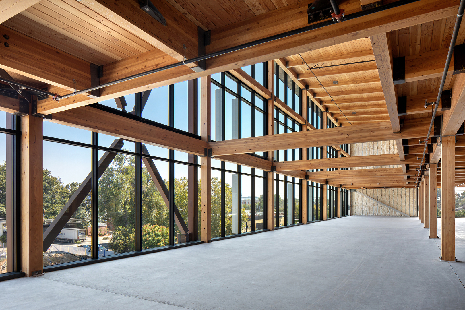
Lumber decking is addressed in IBC Section 2304.9 and generally refers to the use of 1x, 2x, 3x, or 4x lumber, laid flatwise with the wide faces in contact with supporting members, as a floor or roof substrate. A historical method of construction, it goes by several names, such as structural decking, car decking (because of its original use as flooring in rail cars), and simply decking.
SDPWS Section 4.2.8 recognizes three configurations of lumber-sheathed diaphragms to resist wind and seismic loads:
- Single-layer horizontally-sheathed lumber diaphragms (Section 4.2.8.4), constructed of 1x or 2x lumber laid perpendicular to supporting members with nailing in accordance with Table 4.2D and end joints in adjacent boards offset as required
- Single-layer diagonally-sheathed lumber diaphragms (Section 4.2.8.2), constructed of 1x or 2x lumber laid at approximately 45-degree angles to supporting members with nailing in accordance with Table 4.2D and end joints in adjacent boards offset as required
- Double-layer diagonally-sheathed lumber diaphragms (Section 4.2.8.3), constructed with two layers of 1x or 2x lumber; boards in the first layer laid at approximately 45-degree angles to supporting members and boards in the second layer oriented perpendicular to those in the first, both with nailing in accordance with Table 4.2D
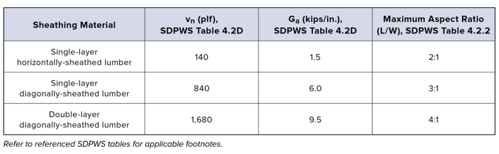
In addition to resisting lateral loads, lumber decking can support gravity loads, achieve a fire-resistance rating, and serve as the exposed finished surface for the space below. However, lumber decking alone may not suffice for the horizontal lateral force-resisting system—e.g., because the load demand exceeds the diaphragm capacity, the stiffness is insufficient, or the aspect ratio is inadequate. Refer to Table 1 for design parameters.
TABLE 1: Nominal unit shear capacity, vn, stiffness, Ga, and maximum aspect ratio (L/W) of lumber-sheathed diaphragm systems
A common solution to this issue is to install a layer of plywood or oriented strand board (OSB) wood structural panel (WSP) sheathing over the lumber decking for use as the structural diaphragm. Lumber decking, particularly when oriented perpendicular to the supporting framing, is much more flexible than a WSP diaphragm and does not effectively share in the load.
Provided the following requirements are met, the exception to SDPWS Section 4.2.8.1 permits this approach, allowing the WSP to act as a blocked diaphragm. The SDPWS requirements include:
- All edges of the overlain WSP must be offset from joints in the lumber decking.
- All adjoining edges of the overlain WSP must be fastened to a common decking member, thus permitting shear load transfer between panels.
- This requirement necessitates careful layout of the decking in new construction or WSP in existing construction.
- The lumber decking must be sufficiently thick to accommodate the minimum nail penetration requirements of SDPWS Table 4.2A.
- Where minimum nail penetration into the decking cannot be achieved, APA Report TT-061 provides guidance indicating that 1.0 in. of penetration in the framing member is sufficient for 8d nails in sheathing up to 23/32 in. thick to achieve full diaphragm capacity. Because this does not meet the minimum nail penetration requirements of SDPWS Table 4.2A, it is prudent to discuss this approach with the building official during design.
- The aspect ratio (L/W) of the diaphragm must not exceed 4:1.
- A continuous load path from the point of application to the final point of resistance must be provided.
- Connections at the diaphragm boundary elements must transfer loads from the WSP diaphragm through the lumber decking, into the boundary framing members, and into the vertical lateral force-resisting system below.
Although not required in the exception to SDPWS Section 4.2.8.1, installation of field fasteners attaching the overlain WSPs to the lumber decking is essential to keep the panels flat during normal service conditions and prevent out-of-plane buckling.
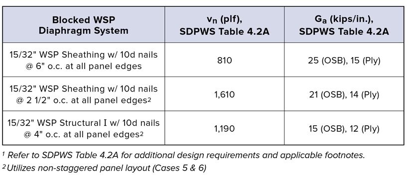
Design capacities are determined using SDPWS Table 4.2A and are the same as those for blocked diaphragms with WSP sheathing attached directly to framing members. Refer to Table 2 for design parameters for several blocked diaphragm systems. Other options are also available.
FIGURE 1: WSP overlay on lumber decking acts as a blocked diaphragm
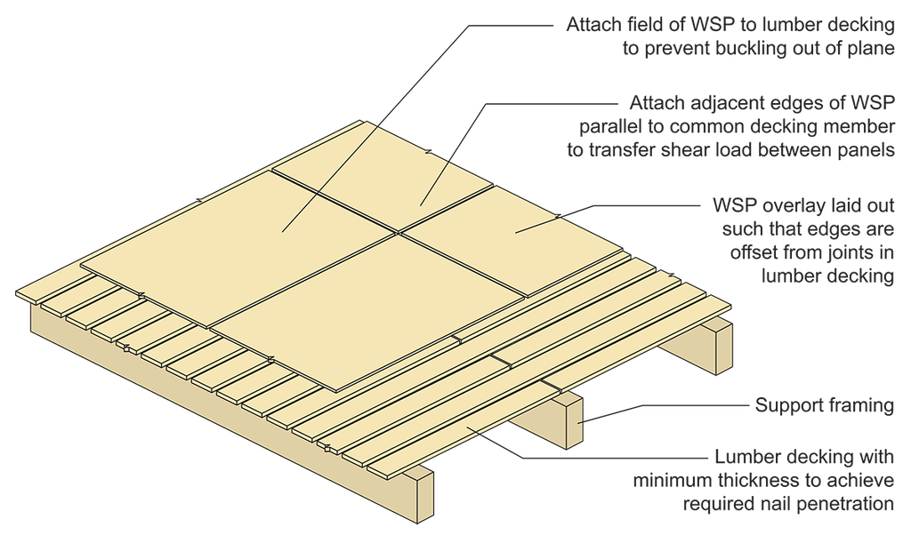
TABLE 2: Nominal unit shear capacity, vn, and stiffness, Ga, of blocked WSP diaphragm systems
Following this guidance, WSP sheathing can be added to lumber decking floors or roofs to increase the diaphragm capacity. This approach can be applied to new structures but is more common in retrofits. For additional discussion on these considerations and more on retrofit conditions, see APA Report TT-097. As permitted by SDPWS Section 4.1.2.1, shear capacity of sheathed wood-frame diaphragms can be calculated using approved alternative procedures, such as those found in ASCE 41, Seismic Evaluation and Retrofit of Existing Buildings.