
Expert Tips
Detailing Non-Bearing Wood Partition Walls Below Floor or Roof Framing
Careful detailing is needed to avoid issues with load resistance at partition walls that were not intended to act as structural elements.
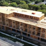
In many wood-frame multi-family and commercial buildings, building layouts result in structural floor and roof spans in the range of 15 feet to 30 feet for floors and much longer for roofs. However, interior partition walls are often required to split interior spaces into separate rooms or units. Structural engineers commonly assume that interior partition walls do not act as load-bearing elements, either due to the potential for future partition re-arrangement or structural inefficiency associated with close support spacings. To avoid issues with load resistance at partition walls that were not intended to act as structural elements, careful detailing is required at the intersection of the top of partition and underside of floor or roof framing.
Reasons for ensuring that load transfer to these partition walls does not occur include avoiding partition wall load-bearing inadequacy and altered shear and moment forces in the floor or roof trusses or joists. Although multiple support locations along a framing system may seem like a positive thing, issues such as inadequate negative moment bracing and unintended truss bottom chord bending can arise if the framing system was not designed for these added support locations. To avoid these issues, detailing the partition to floor or roof framing system typically involves a method of allowing vertical deflection of the framing system without engaging the partition for load-bearing purposes. However, the top of the partition must be braced laterally for horizontal pressures, requiring a unique connection that is rigid for lateral movement but flexible for vertical movement.
In construction with structural steel floor/roof framing and cold-formed steel partition walls, standard methods of accommodating this deflection of the framing system include a deflection track at the top of the wall attached to the underside of the framing system. The partition wall studs are installed such that their tops remain some dimension below the underside of framing (1” is common). Vertically-slotted holes in the sides of the deflection track allow vertical deflection of the framing system and lateral top-of-wall bracing.
In wood construction, several unique detailing considerations exist. For many multi-family projects, floor and roof trusses/joists span from unit wall to unit wall while interior, non-load-bearing walls tend to fall near the center of the floor span. Expected deflections of 1/2″ to 1″ are common for these spans; as a result, these non-bearing walls could end up attracting a majority of the floor load if built tight to the underside of the floor framing system.
Different considerations exist when the partition wall runs parallel to the truss/joist span direction vs. when the wall is perpendicular to the span. Walls parallel to floor/roof spans need to accommodate varying vertical deflections along the span of the framing system. Walls perpendicular to floor/roof spans need to accommodate approximately the same vertical deflection of the framing system.
Following are examples of details that have been successfully used for a variety of partition wall-to-floor or wall-to-roof framing systems:
Wall either perpendicular or parallel to truss/joist spans:
- Prefabricated truss deflection clip such as this example product or this example product
- Cold-formed steel deflection track on top of a wood wall, similar to the condition described above for infill steel partition walls
- For 2×4 wood walls, a 3-5/8″-wide deflection track is typically used. For 2×6 wood walls, 5-1/2″-wide track may be used but is often difficult to source. If 5-1/2”-wide deflection track is unavailable, 6″-wide track could be used. In this case, the gypsum on one side of the wall is extended up into the track or a strip of 1/2” sheathing is installed at the top of the wall.
Walls perpendicular to truss/joist spans:
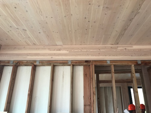
- Partition wall installed such that its top-of-wall elevation is below the bottom of the truss/joist (dimension is based on anticipated framing deflection)
- Between the trusses/joists, blocking is installed on top of the wall plates, attached to the top of the wall but not the trusses/joists. Also, blocking is installed between the trusses/joists on each side of the top of wall, attached to the trusses/joists but not the wall to restrain it against lateral movement but not inhibit vertical movement.
- Structural molding supported off the ceiling on either side of the partition wall, laterally supporting the top of the partition wall while allowing the ceiling to move vertically relative to the top of the wall
Walls parallel to truss/joist spans (but not directly under a framing member):
- Partition wall installed such that its top elevation matches the bottom elevation of the framing system
- Blocking is installed between the trusses/joists at intervals as required, and cut to fit tight between the trusses/joists. This blocking is attached to the top of the partition wall but not to the trusses/joists to allow the wall to be laterally braced at its top and the trusses/joists to deflect down without bringing the blocking down with them.
When partition walls run parallel to and directly under a framing member such as a wood or steel beam or concrete slab, as is common in podium-style elevated floors, a different approach is often taken. More designers are choosing to utilize the provisions of IBC Section 603.1 which permits the use of fire retardant-treated wood wall framing in Construction Types I and II in non-bearing partitions where the required fire-resistance rating is 2 hours or less and in non-bearing exterior walls where a fire-resistance rating is not required. One of the benefits of this approach, particularly in exterior walls, is improved thermal performance. The exterior wood walls below the podium can have the same thermal and building enclosure detailing as those of the wood-frame multi-story building above the podium. Switching the exterior wall framing below the podium to other materials typically requires additional insulation in order to compensate for the difference in thermal performance.
For this condition, common methods of laterally bracing the top of the non-bearing wood walls while accommodating vertical deflection of the structural system above include the use of deflection tracks or prefabricated deflection clips as described above or the use of structural steel angles, either run continuously over the length of the wall or in short sections intermittently placed along the top of the wall. The horizontal leg of the angle is attached to the underside of the structural steel framing or concrete slab and the downward turned vertical leg of the angle is attached to the edge of the wall top plates through vertically-slotted holes.
Regardless of the detail chosen, vertical movement of the structural framing system should also be accounted for in the wall and ceiling finishes. For more information on this, including example detailing options, see the following articles on partition separation: Article 1 and Article 2.
Finally, in addition to structural considerations associated with this partition wall-to-floor/roof framing detail, fire-resistance rating and continuity aspects should be considered. Variables include whether the partition and/or floor or roof assembly requires an hourly rating, whether the partition is a fire partition or fire barrier, and construction sequencing. For more information on this, see this WoodWorks Ask an Expert post.
Related Resources
-
 Hybrid Design: Mass Timber Floor and Roof Panels Over Light-Frame Wood Walls Expert Tips
 -
 Architectural Finishes and Mass Timber: A Primer Expert Tips
 -
 The Modular Enclosure: Protect Your Investment During Every Phase Expert Tips
 -
Exterior Walls in Mass Timber Buildings – Part 1: Code Requirements and Commonly Used Materials Expert Tips