Expert Tips
Accommodating MEP in Exposed Mass Timber Buildings
Options for incorporating MEP in floor and wall panels made from materials such as cross-laminated timber (CLT), nail-laminated timber (NLT), and dowel-laminated timber (DLT).
Mass timber panel products such as cross-laminated timber (CLT), nail-laminated timber (NLT) and dowel-laminated timber (DLT) are used in many applications in multi-family and commercial construction—e.g., floors, roofs, shaft walls, bearing walls and partition walls. In many instances, the panels are left exposed on one side to take advantage of the aesthetic appeal of the timber. For these buildings, accommodation of mechanical, electrical and plumbing (MEP) services is an important design consideration.
Options for Incorporating MEP in Exposed Mass Timber Structures
Accommodating MEP on mass timber walls:
- Fur out a wainscoting wall on the lower half of the mass timber wall to accommodate electrical outlets and plumbing pipes.
- Add light-frame partition walls on one or both sides of the mass timber wall panel to accommodate MEP items, completely covering the mass timber wall panels (note that this can also have acoustical advantages).
- Run the conduit, pipes, etc. on the face of the mass timber wall panels, leaving them exposed and using them as architectural elements.
- Rout and bore the panels to take the electrical conduit, plumbing pipes and mechanical chases. This can be done on site with traditional carpentry tools or in the factory using CNC technology. Structural effects related to panel cross-section reduction should be taken into account.
Accommodating MEP on mass timber floor panels:
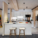
- Run the conduit, pipes, etc. on the face of the mass timber floor panels, leaving them exposed and using them as architectural elements. (See Figure 1.)
- Gap the mass timber panels, running the MEP items between the panels and adding wood ceiling inlay panels between the mass timber panels to conceal the MEP. (See Figure 2.)
- Utilize a raised access floor system on top of the mass timber panels to conceal MEP items. (See Figure 3.)
- Embed items such as electrical conduit and radiant heat tubing in a concrete topping layer cast on top of the mass timber panels. (See Figure 4.)
- For NLT and DLT options, vary the lamination depth (i.e., 2×4 and 2×6 alternating laminations) and tuck smaller MEP items such as conduit and sprinkler lines in the gaps created.
As several of these options include some type of concealed space (e.g., a drop ceiling or raised access floor), it is worth noting that IBC Section 602.4 requires that buildings classified as Type IV construction have no concealed spaces in interior elements (except as permitted for some partitions per IBC Section 602.4.8). For this reason, designers of Type IV mass timber buildings often choose the exposed MEP design solution. However, some Type IV projects have successfully been granted a variance for the use of concealed spaces when those concealed spaces are sprinklered and/or all combustible materials within the concealed spaces (including the mass timber panels) are covered with non-combustible materials such as gypsum wall board.
It is also worth noting that mass timber buildings are not limited to Type IV construction. Type III construction allows the use of mass timber for all interior elements of the building (floors, roofs, partitions, shafts, etc.) and Type V construction allows mass timber throughout the entire building, both for interior elements and exterior walls. Mass timber may also be used in certain locations in Type I and II buildings. For more information on this, see this WoodWorks Ask an Expert post.
Finally, local MEP codes should be checked as they may have an impact on the options available and acceptability of exposed MEP services.
Additional Resources:
For more information and examples of MEPF systems in mass timber projects, see the WoodWorks Solutions Paper: Integrating MEPF in Exposed Mass Timber Buildings.
Further discussion on concealed spaces can be found in the WoodWorks Solution Paper: Concealed Spaces in Mass Timber and Heavy Timber Buildings.
 Figure 1 – Credit: Alex Schreyer |  Figure 2 – Credit: ZGF Architects |
 Figure 3 – WoodWorks |  Figure 4 – Credit: Alex Schreyer |