Expert Tips
Exterior Walls in Mass Timber Buildings – Part 3: Cladding Material Allowances, Types, and Support Details
Detailing considerations for brick, brick veneer, and curtain wall assemblies, including structural supports and connections to mass timber panels
For more information on exterior walls in mass timber buildings, see Part 1: Code Requirements and Commonly Used Materials, Part 2: Common Floor-to-Wall Details, Part 4: Panelization and Part 5: Thermal Enclosure Design
This article references the 2021 International Building Code (IBC) and The Masonry Society’s Building Code Requirements and Specification for Masonry Structures (TMS 402/602-22).
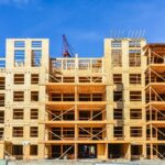
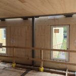
The IBC permits the use of mass timber products throughout Types III, IV and V construction. Structural framing elements in mass timber buildings typically include beams, columns, and floor/roof panels, and one of the great advantages of mass timber is that these elements can often be left exposed on the interior. However, exterior walls are often constructed with other materials. Materials allowed by the code for exterior wall construction, and the required fire-resistance ratings (FRR) of these walls, vary by construction type. This article covers the related code provisions and common types of exterior walls in mass timber projects.
Flexible vs. Brittle Finishes
There are two main categories of exterior cladding: flexible and brittle. Flexible finishes can typically accommodate relatively high levels of movement and require simple detailing. Examples include wood siding, metal panels, and PVC/vinyl siding. Brittle finishes such as brick or stone do not accommodate movement well and can be prone to cracking or other maintenance issues unless properly detailed. There are also finishes that fall between the two extremes. Adhered veneer such as manufactured stone or “thin brick” and glazing systems such as curtain walls and storefront (which tend to have gasketed connections) can all accommodate a certain level of movement. With any of these finishes, it is important to read the manufacturer specifications to ensure the product structure matches or exceeds the performance criteria.
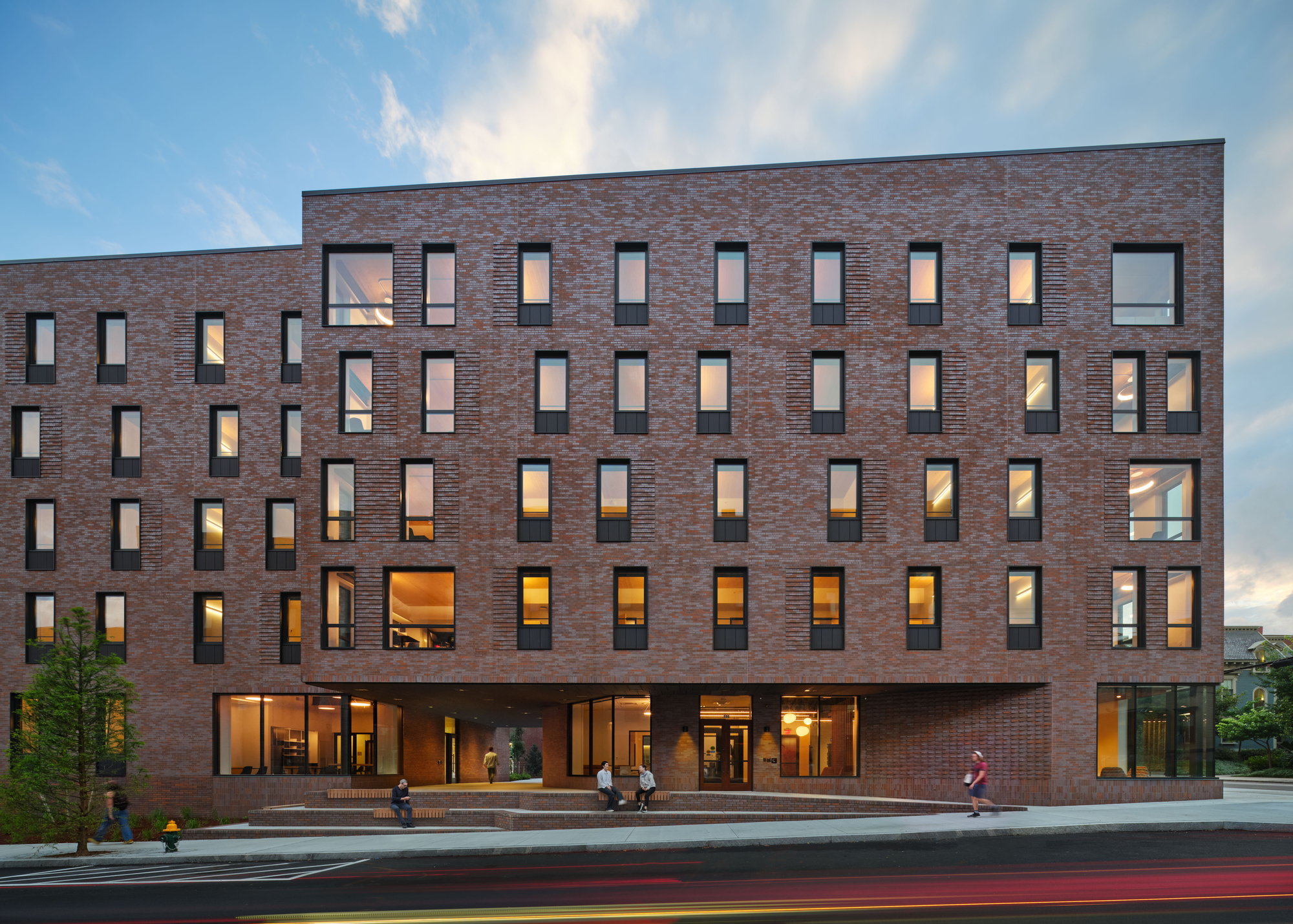
Brick Veneer
Many of the design principles and considerations for brick veneer in light-frame wood buildings can be applied to mass timber buildings. Prescriptively, Building Code Requirements and Specification for Masonry Structures (TMS 402/602-22) allows this type of cladding to be installed up to 30 feet in height (or 38 feet at a gable) without relief. For conditions above 30 feet, Section 12.2.1 provides an alternative method to design anchored veneer. This method can result in a few more feet of height, but not a significant increase. Readers are encouraged to review the WoodWorks paper, Options for Brick Veneer on Mid-Rise Wood-Frame Buildings.
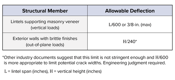
TABLE 1: Allowable deflection limits for brick veneer
Application of The Brick Industry Association (BIA) Technical Note 28 (BIA, 2012) https://www.gobrick.com/media/file/28-brick-veneer-wood-stud-walls.pdf
Relief Angles or Supports
For situations where brick veneer cannot be self-supported, relief angles or supports are required. This relief requires structural support at designated heights throughout the building. For mass timber building systems, a perimeter floor beam is typically inset from the edge of the mass timber floor plate (though some projects may not have perimeter beams at all). Because the beam is inset from the edge, it is more practical to support brick-relieving angles from the mass timber floor panel. In rated floor assemblies, this allows the connection point to occur on top of the floor above the sacrificial char layer of the wood.1 At the location of the relief angle, it is critical to account for movement (shrinkage) of the building and to ensure the panel has adequate stiffness to support the additional weight from the veneer. Refer to Table 2 for potential details with commentary and Figure 1 for an isometric view of the details presented in the table.
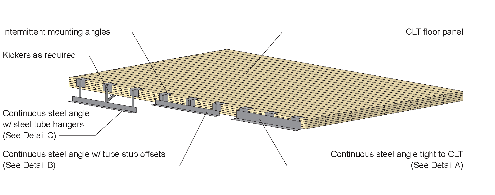
FIGURE 1: Isometric view of possible brick veneer support details (see Table 2 for details)
Brick Ties
Thoughtful selection of intermediate brick ties can help mitigate thermal bridging and moisture movement. Flat, corrugated metal straps can be used as brick ties, but as the building acclimates and shrinks, this can create a slope on the strap for water to travel back toward the building. While this would be a minimal amount of water, over time it can lead to envelope performance challenges. Vertically oriented clips with deformed wires (Figure 2) are another option to mitigate the chance of water infiltration and help mitigate thermal bridging. Minimizing the number of interruptions (ties or supports) in the insulating envelope and the size of those interruptions will help reduce the effects of thermal bridging and potential condensation within the wall cavity.
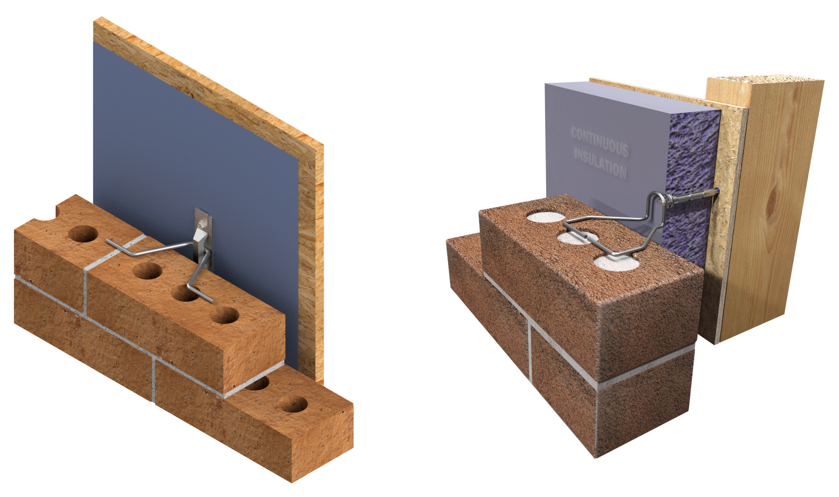
FIGURE 2: Thermal brick ties from FERO (left) and Heckmann Building Products (right)
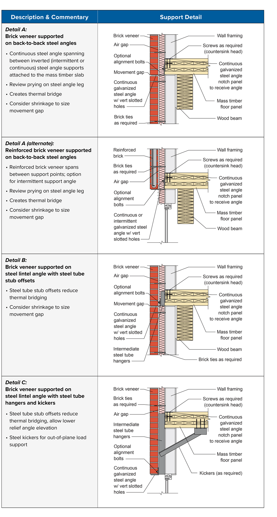
TABLE 2: Brick veneer support details
Curtain Wall
Curtain wall is typically a delegated design item carried out by a specialty engineer and is used in cases where storefront-type glazing systems cannot achieve the desired height (e.g., greater than 10 feet). Curtain wall systems can often be self-supported vertically, but require drift connections to resist out-of-plane forces. For taller structures, the curtain wall system may also need vertical support. The support requirements and deflection criteria should be coordinated with the glazing engineer. Deflection criteria varies between manufacturers, but expect more stringent requirements than code minimums. Fire protection is also a key consideration for curtain wall systems. See WoodWorks’ Mass Timber Fire & Acoustic Database for fire-resistance-rated assemblies and penetrations, including perimeter fire containment systems tested per ASTM E2307.2 It is important to ensure that there are fire and smoke stopping systems in place at the floor plate. This is also typically handled by the curtain wall manufacturer. Figure 3 shows a typical curtain wall bypass condition at a mass timber floor system.
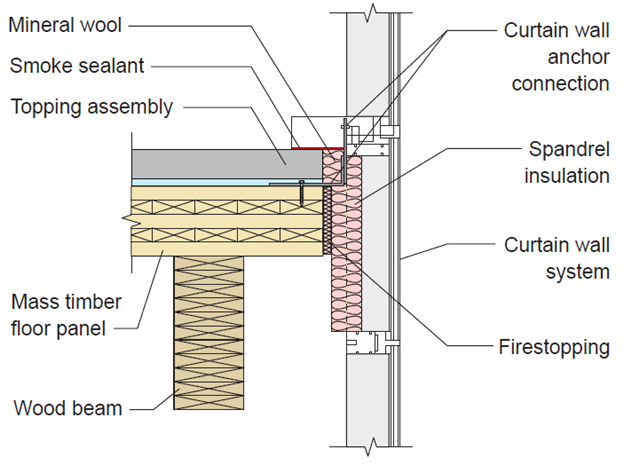
Figure 3: Curtainwall bypass detail at mass timber floor
1In a fire design scenario, the lower layer of a mass timber panel or outer layer of a column or beam may be considered “sacrificial” in that they will char predictably in a fire situation while the remaining wood retains its structural strength, allowing time for occupants to evacuate the building. For more information, see the WoodWorks paper, Fire Design of Mass Timber Members: Code Applications, Construction Types and Fire Ratings.
2ASTM International. (2023). ASTM E2307-20 – Standard Test Method for Determining Fire Resistance of Perimeter Fire Barriers Using Intermediate-Scale, Multi-Story Test Apparatus.