Expert Tips
Design Considerations for Poured Toppings on Mass Timber Floor Panels
Explores key topics such as thickness, reinforcement, and concrete mix design, moisture and structural impacts, acoustic performance, service integration, and fire resistance
This article references the 2024 International Building Code (IBC) and 2021 Special Design Provisions for Wind and Seismic (SDPWS).
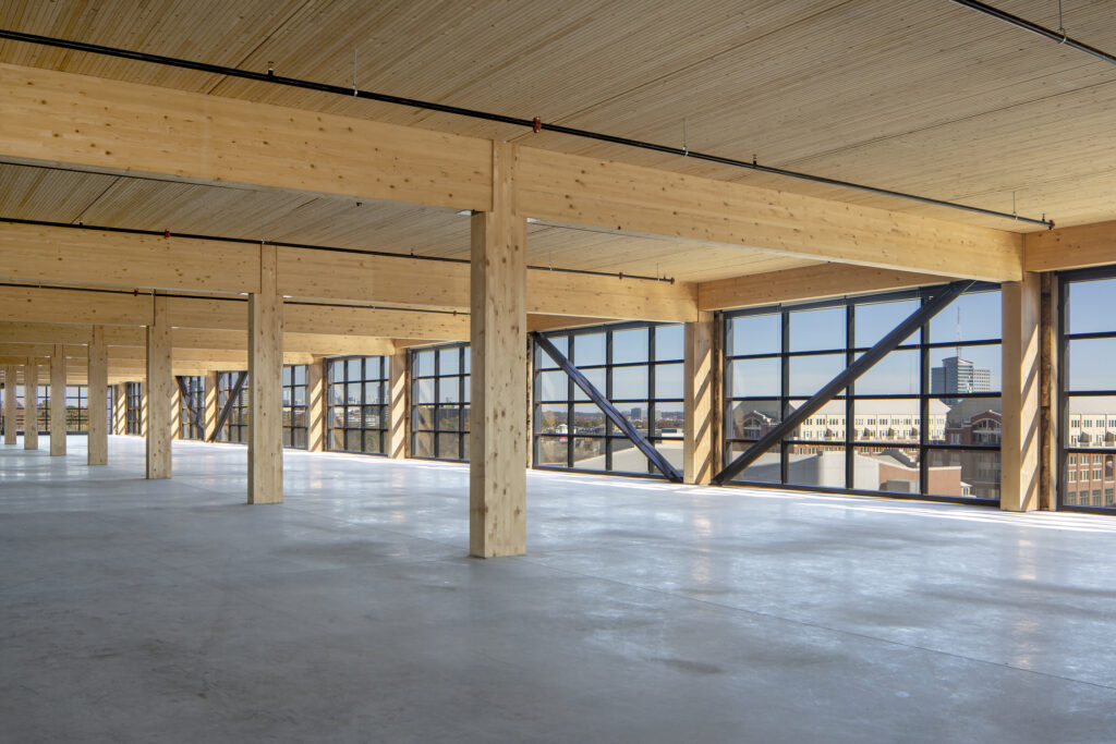
Poured topping slabs made from concrete and gypsum-based materials are common in projects with mass timber floor assemblies. Also known as cementitious toppings, their benefits include increased acoustic performance, a more durable walking surface, and enhanced vibration and floor stiffness. This article discusses various design options and their associated impacts.
Topping Thickness, Reinforcement, and Mix Design
When selecting a poured topping, one of the first decisions is whether to use normal-weight concrete, lightweight concrete, or a gypsum-based material. Thickness is also critical. The topping must be thick enough to perform the necessary functions, but as thin as possible to avoid unnecessary cost, weight, and environmental impacts.
Gypsum-based and lightweight concrete toppings are the lighter options, and typically have a density of about 110-115 pounds per cubic foot (lb/ft3). However, these materials are not durable finish floor surfaces and are only suitable under additional flooring. They are more common in multi-family occupancies than commercial and office buildings. In mass timber buildings, common thicknesses for gypsum toppings are 1.5 and 2 inches, and neither gypsum nor lightweight concrete toppings are typically reinforced. Shrinkage cracking may occur but will not be visible once flooring is installed. Gypsum toppings thicker than 3 inches require two pours and are typically avoided due to the added time and cost.
Concrete toppings can be covered with flooring or sealed and polished for use as the finished walking surface. A normal-weight concrete topping is usually between 1.5 and 3.0 inches depending on the concrete mix and type of reinforcement (though thinner toppings have been used). The American Concrete Institute’s 302.1R-15, Guide to Concrete Floor and Slab Construction (ACI, 2015) provides recommendations on topping construction. When the topping is poured on an acoustic mat or other similar material, it is typically assumed to be unbonded.
Some engineers prefer the use of rebar reinforcement—such as #3 at 18 inches on center each way—with chairs installed to achieve minimum cover requirements. Others prefer fiber reinforcement. Welded wire fabric is less common in toppings on mass timber floor panels; if used, it requires adequate chairs to maintain clear cover beneath the reinforcement. Performance of the reinforcement relative to crack control and shrinkage should not be overlooked, especially when the concrete topping will be the exposed walking surface. When selecting reinforcement type, it is important to consider the stiffness and anticipated deflections of the mass timber floor panels and supporting beams. Some engineers prefer the use of fiber reinforcement only in stiffer systems where deflections are anticipated to be low, similar to a slab-on-grade rather than slab-on-deck scenario.
Concrete strength and other mix specifics also vary with the project needs. When the concrete will be the exposed walking surface, a mix of 4000 pounds per square inch (psi) is common. When there will be an applied finish floor, 4000 psi is still common, but some project teams have used a lower strength mix, such as 3000 psi.
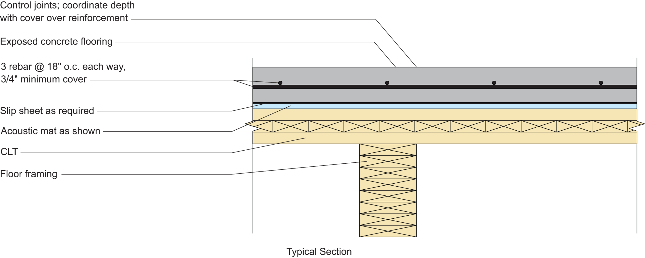
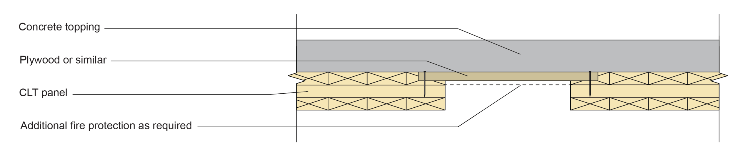
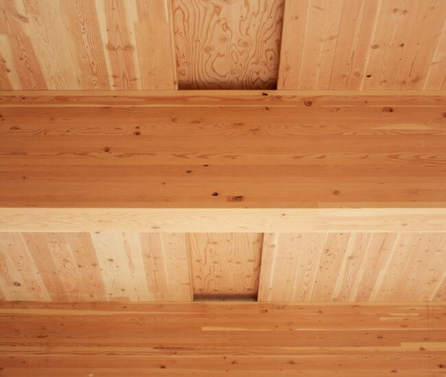
Typical mass timber floor assembly with concrete topping
Where the exposed topping will be the finish floor, the designer may choose a polished finish. In this case, ACI 310.1-20, Specification for Polished Concrete Slab Finishes (ACI, 2020), provides information that may be incorporated into the project specifications.
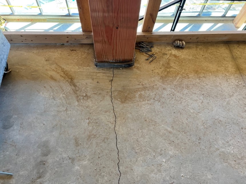
Crack Control in Concrete Toppings
Effective crack control in concrete topping slabs over mass timber floor decks is essential to ensure long-term serviceability, durability, and aesthetic performance. This becomes particularly critical when the concrete is left exposed as the finished floor surface, where uncontrolled cracking can detract from visual quality and compromise surface integrity. A common approach involves installing contraction joints at regular intervals in the concrete. These joints help manage shrinkage-induced and thermal cracking by concentrating cracking at predefined locations, which are hidden within a surface cut. A commonly referenced guideline in older editions of ACI 302.1R is to place contraction joints at intervals no greater than 24 to 36 times the slab thickness (in inches), and that they should be placed as soon as the concrete can support tooling. For a 4-inch thick topping, this equates to spacing joints no more than 8 to 12 feet apart. Joint layout should coordinate with the underlying timber structure to maintain alignment and structural integrity. To mitigate cracking due to deck flexure, these contraction joints are often aligned over primary beams and girders with intermediate control joints spaced as needed.
Alternatively, there are several strategies to minimize cracking or distribute shrinkage-induced cracking among many small cracks instead of fewer large cracks. Shrinkage-compensating concrete mixes can mitigate the formation of cracks by reducing the volume changes due to shrinkage while curing and drying. When coupled with proper curing methods, such as continuous moist curing for a minimum of seven days, the risk of early-age cracking is significantly reduced. Reference ACI 308R-16 and similar for more information. Reinforcement strategies also play a key role in crack control. Deformed steel reinforcing bars, welded wire reinforcement (WWR), or fiber reinforcement can be used to distribute stresses more evenly and control the width and propagation of cracks. While reinforcement does not prevent cracking entirely, it helps maintain crack widths within acceptable limits. Strategic placement of reinforcement, especially at locations of anticipated stress concentration such as openings and supports, enhances overall slab performance and longevity. In non-structural toppings, selection of the reinforcing is often left to the architect and/or contractor based on their experience and expertise in the unique finish requirements of the end product. Project mock-ups can help ensure the reinforcing is adequate.
Levelness and Flatness of Topping Slabs
When a concrete slab is cast on a suspended, unshored floor in a concrete building or steel building with slab on metal deck, the designer can specify floor flatness (FF) tolerances but not floor levelness (FL). FL is appropriate only for slabs-on-ground and shored, non-cambered slabs; in the latter scenario, measurements must be taken prior to removing the shores. The structure deflects when the shoring is removed, so levelness is guaranteed only at that initial point in time and not when follow-on trades start their work.
Following is an excerpt from ACI 302.1R-15, Guide to Concrete Floor and Slab Construction, Section 10.15.3.2:
The FL tolerance should only be applied to slabs-on-ground that are level and suspended slabs that are both level and shored at the time data are taken. The FL levelness tolerance should not apply to slabs placed on unsupported form surfaces or be applied to cambered or inclined slab surfaces. Concrete slabs placed over unshored structural steel and metal deck surfaces can exhibit significant deflection in the hardened state. The resulting slab surfaces have occasionally required extensive repair to achieve a product satisfactory for applied finishes or partitions.
However, the focus of this article is not assemblies containing a concrete structural slab or slab-on-deck, but rather those with a topping slab on mass timber floor panels. ACI does give recommendations for how to obtain a level suspended floor using a two-course placement. In this system, the topping slab is placed using slab-on-ground techniques after the shoring has been removed (e.g., after the structure has deflected, including the base course). One could argue that a topping slab on a mass timber floor panel is a similar situation, but it will depend on the stiffness of the floor and how much deflection is anticipated under the weight of the topping. If the topping is thin enough and the mass timber floor stiff enough, it might be feasible for the contractor to meet a specified FL number. However, this is not common and typically not recommended as it is considered unreasonable to hold a contractor responsible for the deflection of the structure. For mass timber projects where topping slab levelness is critical, specifying a self-leveling compound in addition to the base concrete topping is an option.
Moisture Impacts of Toppings on Mass Timber Floor Panels
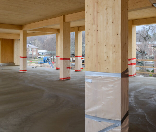
When using poured concrete or gypsum-based toppings on mass timber panels, it is important to consider the moisture impacts of the topping on the mass timber, both during construction and over the long term. Most mass timber projects utilize a floor assembly consisting of (from top to bottom) a finish floor (if applicable), the concrete/gypsum topping, an acoustic mat, and the mass timber panel. For this type of assembly, it is not typical to install a vapor barrier between the mass timber and poured topping because, while the acoustic mat is generally not intended to function as a true vapor barrier, it does provide some separation. If there is no acoustic mat, joints at panel edges would likely need to be taped and pour stops installed to keep the topping from seeping through the assembly during the pour. In most cases, some type of barrier is used to accomplish this and to provide a level of moisture protection between the mass timber and concrete. The mass timber and topping manufacturer should be consulted for additional recommendations.
A related consideration is the moisture content of the mass timber when the topping is poured. Not allowing the mass timber to dry adequately prior to installing the acoustic mat and topping could result in trapped moisture, which creates the potential for long-term durability issues.
In the document, Moisture Risk Management Strategies for Mass Timber Buildings Version 2 (RDH, 2022), engineering consulting firm RDH Building Science recommends waiting to install the acoustic mat and poured topping until the moisture content of the mass timber is 16% or less. Section 7.6 of the Nail Laminated Timber U.S. Design & Construction Guide (BSLC, 2017) recommends the same.
Several studies have been performed to monitor the moisture content of mass timber during construction and in service. For example, moisture content monitoring was conducted on Carbon12, an eight-story mass timber building in Portland, OR. The findings are presented in the report, Structure Moisture Monitoring of an 8-Story Mass Timber Building in the Pacific Northwest (Kordziel et al., 2019), which concludes that the concrete topping had little effect on the moisture content of the cross-laminated timber (CLT). Moisture content monitoring was also performed on Brock Commons, an 18-story mass timber and concrete student residence hall on the campus of the University of British Columbia in Vancouver, BC. Findings from Carbon12, Brock Commons, and other North American projects are discussed in Monitoring Moisture Performance of Cross-Laminated Timber Building Elements during Construction (Schmidt & Riggio, 2019), which states:
Data from the SHM study at Brock Commons—which began construction summer of 2016—showed that after one year the vast majority of floors—which were topped with a concrete screed—were in-between 16%-20% [moisture content] (averaging about 16%), and after the second year the majority of these had dried to below 16% (averaging about 13%). These data show that drying in floor locations was slow after the concrete screed and respective assemblies were installed. Factors at Brock Commons that favored hygrothermal performance included erection in summer, high level of standardization and prefabrication, which included the installation of the façade coincident with erection of framing, self-sheltering of floors, the use of wax at end grain/hardware cut-outs, and the application of a vapor-permeable coating on all CLT surfaces.
Carbon12 was erected in winter during record rainfalls in Portland, and many sensors installed in cut-outs of the CLT floors were damaged by ponding water. The data from sensors that maintained readings, however, were corroborated with laboratory experiments and hygrothermal simulations, and suggest three critical points about CLT moisture performance:
- Floor elements erected earlier in construction showed much higher MC gain and longer periods of time spent above the fiber saturation point, than the roof erected later
- In CLT floors, while the upper-most plies showed the most gains, all ply depths showed some MC vulnerability, with much slower drying rates at the interior layers
- Similar building member types tended to display high variability relative to one another in MC gain and loss
The method for lowering the moisture content of installed mass timber members should be carefully selected. Many teams use air drying (i.e., letting the elements dry naturally to acclimate to environmental conditions). Dehumidifiers can be used in particularly wet regions, but it is important not to dry the wood too quickly. Drying panels too quickly at a low relative humidity can cause their surface to dry faster than the inner layers, resulting in surface splitting and checking. Similar issues can occur with columns and beams.
Structural Impacts of Toppings on Mass Timber Floor Panels
Toppings contribute to the structural needs and performance of mass timber floor panels. A 3-inch-thick slab of normal-weight concrete has a dead load of approximately 37.5 pounds per square foot (psf). This essentially triples the dead load of the assembly, as a 5-ply CLT floor panel has a self-weight of approximately 18 psf. These added dead loads also have an impact on seismic loads and foundation requirements.
The structural design of a mass timber floor assembly is often governed by vibration rather than bending capacity, and a poured topping can also benefit vibration performance. WoodWorks U.S. Mass Timber Floor Vibration Design Guide notes the following:
Adding mass to the constructed assembly is a common approach for improving vibration performance for mass timber floors (e.g., concrete topping), but care must be taken to ensure the fundamental frequency of the floor is not reduced to frequencies near resonance, offsetting the benefit of additional mass.
For more information on the vibration impacts of concrete toppings on mass timber floor panels, see Chapter 3 of the vibration guide referenced above.
On projects with very high diaphragm forces, particularly in high-seismic regions, a concrete topping is sometimes used as the structural diaphragm. In this situation, the topping must have adequate thickness and reinforcement to resist the diaphragm forces. It must also be adequately attached to the mass timber floor panels or other supporting construction to provide a complete lateral load path. Before taking this approach, acoustical analysis may be warranted. Attachments between the concrete topping and mass timber could negatively impact the acoustical performance of the assembly since the primary purpose of the acoustic mat is to create separation and attachments circumvent that.
Note that mass timber floor panels can also be used as the structural diaphragm. The American Wood Council’s 2021 Special Design Provisions for Wind and Seismic (SDPWS) includes provisions for the design of CLT diaphragms, and WoodWorks’ CLT Diaphragm Design Guide provides insight into their analysis, design and constructability.
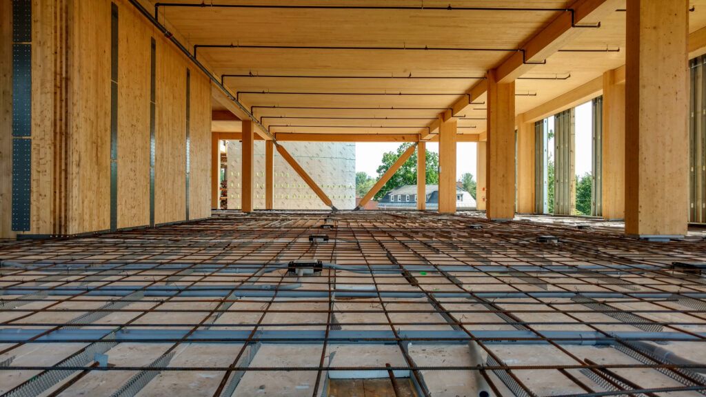
A concrete topping can also be structurally integral with a mass timber floor panel under gravity loading in a configuration referred to as timber-concrete composite (TCC). This option requires structural connection between the timber and topping, which can be achieved with steel mesh plates, inclined screws, plates with headed studs, or other means. Because the slab is loaded with gravity forces, the timber goes into tension and the concrete goes into compression. This leverages the strengths of each material and results in a slab that is stiffer and can generally span further than a system where the timber and topping are structurally independent.
TCC floor systems may also include other materials. For example, the floor system at the John W. Olver Design Building at UMass Amherst includes 5-ply CLT panels, 1 inch of rigid insulation on top of the CLT (for acoustic performance), and 4 inches of reinforced concrete. For TCC design information, the Design Guide for Timber-Concrete Composite Floors in Canada is a useful resource.
Acoustics
A common reason to include a poured topping layer on a mass timber floor assembly is to improve acoustic performance by decreasing the amount of sound that can pass through the assembly. Bare mass timber floor/ceiling or wall assemblies are seldom used, in large part due to inadequate acoustic performance. For example, a 5-ply CLT floor with a thickness of 6.875 inches has a Sound Transmission Class (STC) rating of 41 and an Impact Insulation Class (IIC) rating of 25. The code minimums are STC 50 and IIC 50 for multi-family occupancies, per IBC Section 1206.
One of the benefits of mass timber is its relative light weight, meaning that foundations and/or soil remediation work can often be minimized when compared to heavier structural materials. However, with acoustics, more mass typically means better noise control. For comparison, a 6-inch-thick concrete slab weighs approximately 80 psf and has an STC rating of 53 while a 6.875-inch-thick CLT panel weighs about 18 psf and has an STC of 41. Due to the lack of mass inherent in the mass timber panel, the added mass from a poured topping greatly increases the acoustical performance of the floor/ceiling assembly.
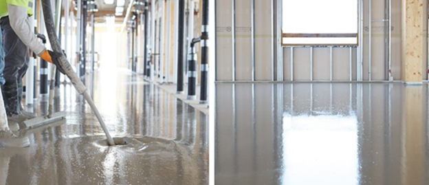
Gypsum concrete floor topping in a mass timber building / Photos USG
As noted, it is common to place an acoustical mat between the mass timber panel and topping. The mat functions as a resilient break, decoupling the two slabs and improving acoustic performance. For more information on the design of mass timber assemblies for acoustics, see WoodWorks’ Acoustics and Mass Timber: Room-to-Room Noise Control and Mass Timber Fire and Acoustic Database. The database features more than 500 acoustically-tested assemblies, including details on the relative impacts of different topping types and thicknesses.
MEPF Integration
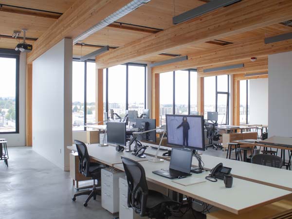
Since mass timber structure is often left exposed, it is important to creatively integrate or hide mechanical, electrical, plumbing, and fire-protection (MEPF) systems. Electrical conduit and radiant heat tubing can be hidden within the topping slab. However, it is important to account for their presence when determining topping thickness and designing for acoustical performance. For more information, see the WoodWorks article, Accommodating MEP in Exposed Mass Timber Buildings.
When routing conduit through a topping slab, it is crucial to acknowledge the lost future flexibility of electrical within the interior space. For example, on one speculative mass timber office building, significant portions of the topping had to be removed as part of tenant fit-up, since the installed conduit did not meet the needs of the new tenant. One option to minimize re-work is to install toppings as part of the tenant improvement package rather than the core and shell.
Fire Resistance
The ability of mass timber elements to char during a fire while retaining their structural strength means that, in most scenarios, they can achieve the fire-resistance rating (FRR) required by the building code without factoring in a poured topping. For information on the FRR requirements of mass timber members, and the design options available, see WoodWorks’ Fire Design of Mass Timber Members: Code Applications, Construction Types and Fire Ratings and Demonstrating Fire-Resistance Ratings for Mass Timber Elements in Tall Wood Structures.
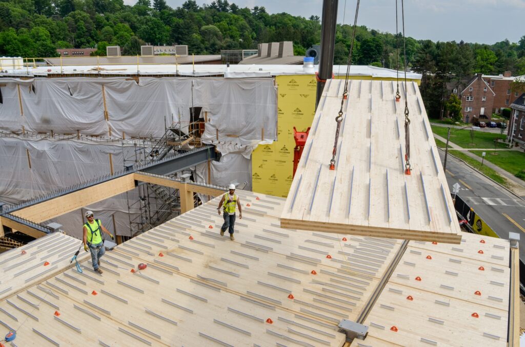
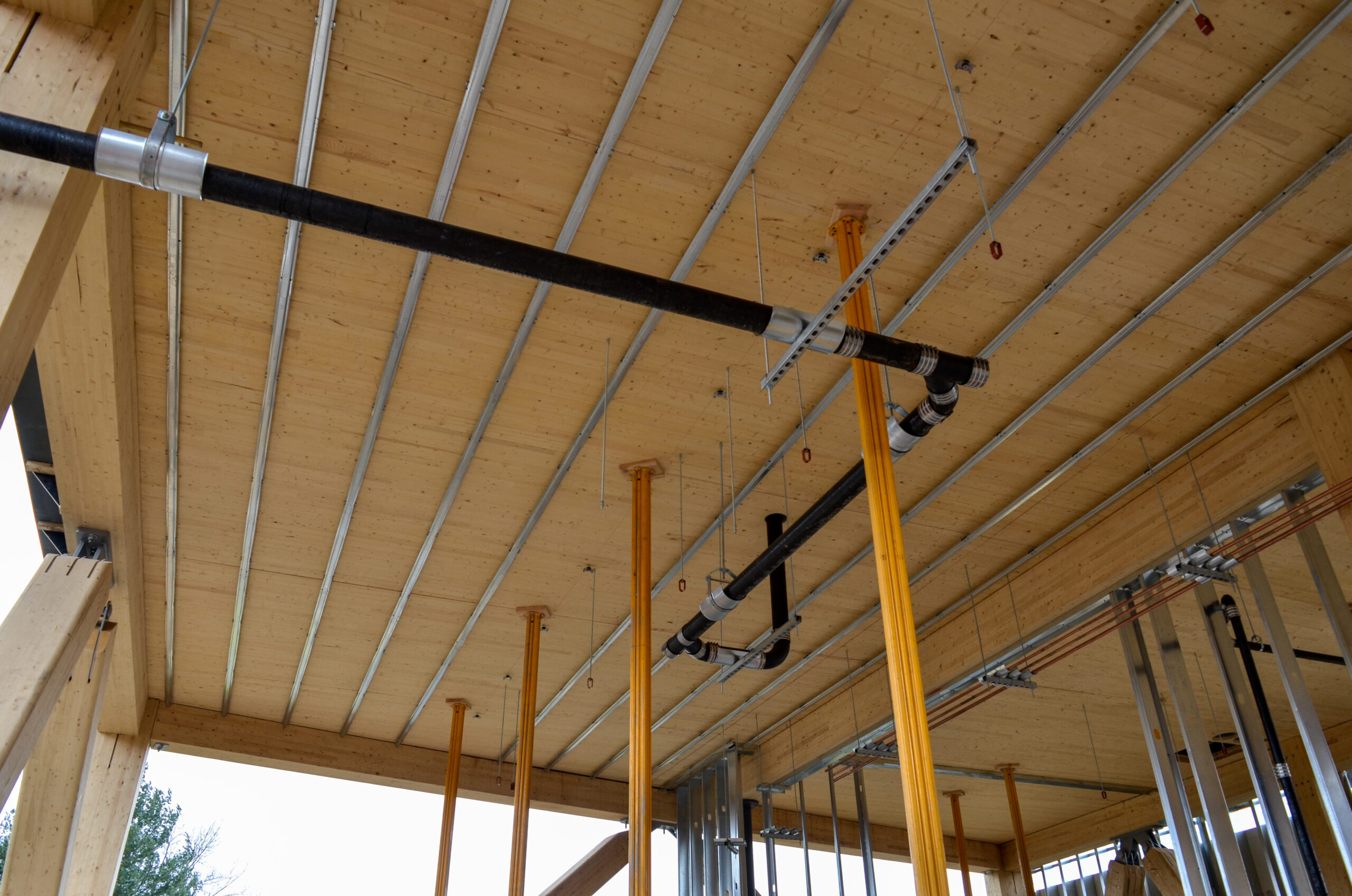
However, in certain applications, a design team will choose to neglect the inherent fire resistance of the mass timber and have the poured topping provide the FRR. For example, this may be the case if the assembly includes sizeable gaps between mass timber floor panels to run electrical conduit, data cabling, and sprinkler lines. In this scenario, a plywood panel would be installed on top of the mass timber panels to cover the gaps and serve as a base for the topping. Removable ceiling panels or other ceiling finishes would be installed within the gaps from below to conceal the services. Since the mass timber panels do not form a uniform plane across the entire ceiling area, the concrete topping would be used to provide the FRR. IBC Table 722.2.2.1 shows the required concrete slab thicknesses for hourly FRRs of 1 to 4 hours.
To help building designers evaluate the options for fire-tested assemblies, WoodWorks has compiled known and publicly available tested systems in its Mass Timber Fire & Acoustic Database. The database includes options with and without poured toppings
While it is generally agreed that a poured topping material is not required for a mass timber floor system to achieve an FRR, the topping may still provide benefits from a fire performance perspective, such as preventing the passage of smoke or hot gases.
Example mass timber floor assembly with gapped panels where the concrete topping provides the assembly FRR
Shoring Requirements
Unless a topping is being used structurally as part of a TCC system, the floor will not typically need to be shored during the pour. In non-TCC applications, the mass timber floor slabs are designed to fully support the dead load of the topping and are therefore adequate to support the slabs during pouring, curing, and afterwards. When the topping is being used structurally as the diaphragm, the mass timber floor panel may be adequate to function temporarily as the diaphragm while the topping cures.
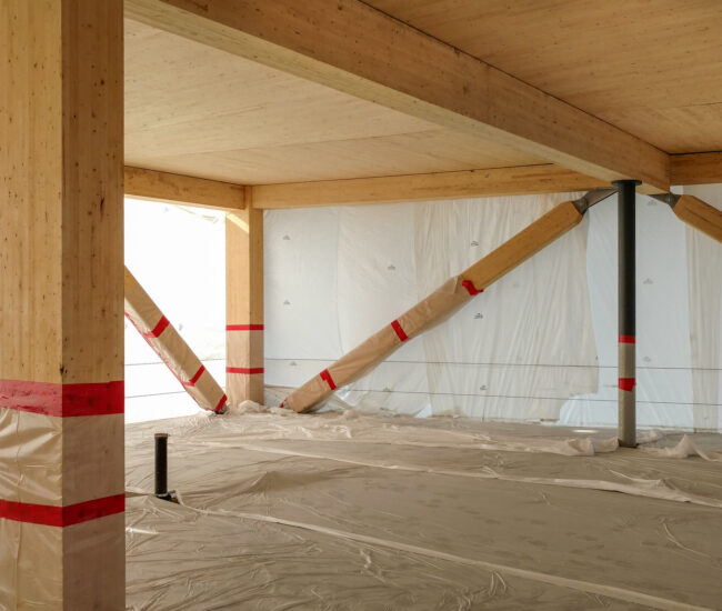
However, in a TCC system, the structural performance of the topping slab is necessary to achieve the full gravity capacity of the floor assembly. The mass timber floor panel will likely need to be shored while the topping is poured and until it fully cures unless the panel has been designed to support the full dead load of the topping. Since mass timber construction is often fast-tracked to take advantage of the prefabricated nature of the timber elements, it is important to consider the impact of temporary shoring on the schedule, including the fact that work may be delayed on lower levels while shoring is in place.
Temporary shoring installed on CLT floor panels used in a TCC system at the John W. Design Building / Photo Alex Schreyer
Embodied Carbon Impacts
One of the benefits of mass timber is its relatively low embodied carbon. For information on calculating the embodied carbon of different structural systems, see the WoodWorks article, Carbon Accounting Tools for Structural Systems.
The embodied carbon impact of a poured topping shouldn’t be overlooked when designing a mass timber floor assembly, or when deciding whether a topping will be used. A life cycle assessment (LCA) study of the Burwell Center for Career Achievement in Denver, CO assessed the environmental impacts of different structural systems. This project was built as a three-story mass timber structure. The LCA assessed the environmental impacts, in terms of global warming potential (GWP), and cost differences between the as-built mass timber structure and an alternative structural steel with concrete slab on metal deck design. The full LCA and cost results are available here.
The LCA concluded that the GWP of the mass timber structure was significantly lower, 31%, than for the alternative structure. Notably, when considering just the structure above the foundation, the GWP of the mass timber structure was found to be 80% lower than the steel structure. Interestingly, most of the GWP impact of the mass timber structure was not due to the mass timber itself, but the concrete topping. As noted in the LCA report:
The concrete topping slab on the CLT floor is the main contributor to the mass timber system’s GWP. It accounts for 81% of the superstructure’s structural GWP impact but only 50% of the superstructure’s mass (27% of the building’s total concrete mass).
While some designers have expressed interest in eliminating poured toppings because of the environmental impacts, the added mass may be necessary to achieve the required acoustic performance. Understanding the environmental impacts of different poured toppings (e.g., normal-weight concrete, lightweight concrete, and gypsum-based) can help a design team make an informed decision based on the project objectives.
References
American Concrete Institute (ACI). (2015). 302.1R-15, Guide to Concrete Floor and Slab Construction.
American Concrete Institute (ACI). American Society of Concrete Contractors. (2020). ACI 210.1-20, Specification for Polished Concrete Slab Finishes.
American Wood Council (AWC). (2021). 2021 Special Design Provisions for Wind and Seismic.
Binational Softwood Lumber Council (BSLC). (2017). Nail Laminated Timber U.S. Design & Construction Guide.
International Code Council (ICC). (2024). International Building Code.
Kordziel, S., P. Shiling, S.V. Glass, S. Zelinka, P.C. Tabares-Velasco. (2019). Structure Moisture Monitoring of an 8-Story Mass Timber Building in the Pacific Northwest. Journal of Architectural Engineering.
RDH Building Science. (2022). Moisture Risk Management Strategies for Mass Timber Buildings Version 2.
Schmidt, E., M. Riggio. (2019). Monitoring Moisture Performance of Cross-Laminated Timber Building Elements during Construction. Wood Science and Engineering Department, College of Forestry, Oregon State University.