
Protective Design
Blast & Forced Entry/Ballistic Protection
Buildings that house critical assets often have to meet blast as well as forced entry/ballistic resistance (FE/BR) design requirements to mitigate the hazardous effects associated with terrorism. Historically, these buildings have been constructed using concrete and steel. A significant amount of testing has been performed to demonstrate the ability of these building materials to resist blast and FE/BR threats. Fewer tests have been performed on wood construction for similar threats. At least part of this stems from the relative difficulty of designing light-frame wood construction to resist these threats efficiently and economically.
However, the emergence of mass timber construction, and cross-laminated timber (CLT) in particular, both in the U.S. and internationally, presents an opportunity to provide a sustainable building material alternative to owners and architects developing high-security buildings. The solid, panelized nature of CLT allows for both inherent strength and ease of construction. Further, as connections for CLT panels typically consist of steel and timber elements, ductile energy-absorbing panel attachments are relatively easy to design.
Past U.S. Forest Service-sponsored efforts have been used to generate design guidance for CLT construction exposed to blast loads—i.e., Protective Design Center Technical Report (PDC-TR) 18-02: Analysis Guidance for Cross-Laminated Timber Construction Exposed to Airblast Loading (PDC-TR 18-02), published by the U.S. Army Corps of Engineers. Additionally, testing funded by a 2019 Wood Innovation Grant demonstrated the feasibility (in terms of performance, cost, and weight) of embedding thin steel plates within a CLT panel to defeat Department of State (DoS) blast, ballistic, and forced entry threats. Below is a summary of the testing performed to date, along with pertinent reports and references.
Blast Protection
Blast design requirements are specific to a facility’s governing jurisdiction and defined in various standards. Several well-known standards pertinent to blast design include:
- UFC 4-010-01: U.S. Department of Defense (DoD) blast design requirements for antiterrorism
- UFC 3-340-02: U.S. DoD blast design requirements for accidental explosions of ammunition or explosives
- ISC Risk Management Process: Non-military U.S. federal government blast design requirements for U.S. facilities
- OBO Building Code: U.S. DoS blast design requirements
- ASCE 59-11: Blast design requirements for non-government facilities
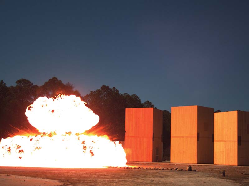
Blast testing of CLT panels to this point has largely focused on the U.S. DoD antiterrorism requirements included in UFC 4-010-01 (2013); however, blast testing to meet other blast design requirements is underway. Highlights from several blast tests performed to date are included in the following videos:
Video of Blast Test 3:
In this test, the timing of the negative phase blast loading aligned with the wall panel’s rebound response, which led to a greater displacement response in rebound than in inbound. This test underscores the importance of designing CLT wall panel connections potentially exposed to blast loading for both inbound and rebound response, particularly for load-bearing CLT wall panels.
Video of Blast Test 5:
This test was identical to Test 3, except an axial preload of roughly ten percent of F’cAparallel was placed on the CLT wall panels facing the detonation. Whereas the Test 3 wall panels ruptured, the Test 5 wall panels did not, illustrating the positive effect of axial load on the displacement response of CLT panels dynamically stressed near their elastic limit.
Video of Blast Test 7:
Test 7 was designed to rupture 5-ply CLT wall panels installed on one of the three CLT test structures. As the other two structures had much weaker wall panels facing the detonation (i.e., 3-ply CLT and 2×4 nail-laminated timber (NLT)), this test illustrated the response of mass timber panels that were intentionally overloaded by the imposed blast loading.
Video of Blast 7-ply Test:
7-ply Test was designed to displace 7-ply CLT wall panels well beyond their elastic limit. The test indicated that, even at a displacement ductility of 3, the hazardous debris associated with 7-ply CLT panels is negligible.
How do I design CLT for blast loads?
PDC-TR 18-02: Analysis Guidance for Cross-Laminated Timber Construction Exposed to Airblast Loading gives engineers trained in structural dynamics information they need to analyze and design CLT structures for blast loads. WoodWorks participated in the testing that led to this document, and has also created resources to assist engineers seeking to use it.
- PDC-TR 18-02 – U.S. Army Corps of Engineers
- New for DoD Designers: Structural Design of Mass Timber Exposed to Blast Loads – WoodWorks webinar
- Overview of PDC-TR 18-02 – WoodWorks paper
Findings from Blast Tests Performed to Date
Mass timber structural systems can effectively resist blast loads in the elastic range with little noticeable damage. Due to the relatively high strength and low stiffness of mass timber panels, significant blast loads can be resisted by mass timber panels in the elastic response range.
The post-peak response of mass timber panels is relatively brittle. However, for CLT systems, the presence of multiple plies allows for measurable residual strength following initial panel rupture. Additionally, the two-way action inherent in CLT provides a means for load distribution across the panel, thus limiting the damage at the location of peak applied load. NLT systems do not have this advantage of cross lamination and thus do not exhibit these post-peak response benefits.
Provided fastener penetration is of sufficient depth, significant blast loads can be resisted and transferred through CLT connections that are both simple and quick to install. An added benefit is that dowel-type connection limit states associated with CLT construction are often ductile in nature due to the propensity for wood to crush and/or steel to yield when loaded in shear beyond their respective elastic limits.
The results of the blast demonstration testing indicate that single degree-of-freedom (SDOF) dynamic analysis can be used to approximate the peak out-of-plane displacement of CLT panels without openings. The static and dynamic increase factors used to approximate the expected ultimate resistance defined in PDC-TR 18-02 show good correlation with arena blast test results.
Load-bearing CLT panels that exhibit localized panel rupture due to blast loading are capable of resisting their service axial loads provided the panel’s displacement ductility is limited to two.
The rebound response of CLT panels often controls over its inbound response, thus highlighting the importance of considering the negative phase of blast loading when designing CLT components and systems for blast loading.
Visually-graded CLT panels demonstrate significantly greater out-of-plane bending strength than that associated with the characteristic values defined in ANSI/APA PRG 320 Standard for Performance-Rated Cross-Laminated Timber.
While the testing conducted to this point provides a solid foundation upon which to base blast design guidance for CLT structures, the following areas of additional research would serve to curtail conservatism in the analysis and design approaches for such structures:
- The minor strength direction bending strength values for CLT panels in Annex A of PRG 320 appears to be too conservative from an ultimate response perspective. Further testing to justify more representative peak bending strengths in the minor strength direction may allow for openings in blast-loaded structures to be designed more economically. Additionally, better quantification of the minor strength direction strength and stiffness will enable more explicit consideration of the two-way action inherent in CLT construction.
- Additional blast testing on 5-ply, 7-ply, and 9-ply panels is necessary to assess the robustness of the SDOF resistance function methodology defined in PDC-TR 18-02.
- Dynamic characterization of different timber species and dowel-type connections at blast-relevant strain rates will assist in refining the dynamic increase factors (DIFs) used in design.
Download blast test reports below.
Ballistic Protection
Ballistic design requirements are specific to a facility’s governing jurisdiction and defined in various standards. Several well-known standards pertinent to ballistic design include:
- STD-SD-01.01, Revision H: U.S. DoS ballistic design requirements
- UFC 4-023-07: U.S. DoD design guidance for direct fire weapons
- ASTM F1233: Test procedure for ballistic impact
Much of the ballistic testing on CLT panels performed to date has focused on U.S. military expeditionary structures and DoS facilities.
Findings from Ballistic Tests Performed to Date
Through a series of ballistic tests performed on softwood CLT targets, Sanborn et al. (2019) discovered that the equations in UFC 4-023-07 consistently overpredict the penetration of spherical steel projectiles by a wide margin. (K. Sanborn, T. R. Gentry, Z. Koch, A. Valkenburg, C. Conley and L. K. Stewart, “Ballistic Performance of Cross-Laminated Timber (CLT),” International Journal of Impact Engineering, vol. 128, pp. 11-23, 2019.)
CLT panels can be modified to defeat the ballistic threat defined in SD-STD-01.01 in a relatively cost-effective fashion. Among the candidate panel designs considered, the optimal means of defeating these projectiles is by introducing steel plates into the layup. While the addition of steel plates adds cost, the cost markup associated with integrating plates is smaller than introducing wire mesh or species of hardwood that could defeat the DoS ballistic threat projectiles.
Download the ballistic test report below.
Forced Entry Protection
Forced entry design requirements are specific to a facility’s governing jurisdiction and defined in various standards. Several well-known standards pertinent to forced entry design include:
- STD-SD-01.01, Revision H: U.S. DoS forced entry design requirements
- UFC 4-026-01: U.S. DoD forced entry design requirements
- ASTM F1233: Test procedure for blunt/sharp tool impacts
Only one known forced entry test has been performed on CLT to date, which is described below.
Findings from Forced Entry Tests Performed to Date
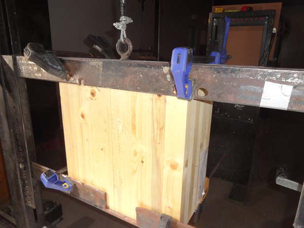
A standard 7-ply CLT panel consisting of No. 2 SPF-S lumber in both the major and minor strength directions resisted a FE attack performed in accordance with SD-STD-01.01 for 44 minutes. As most elements in U.S. DoS facilities only require a 15-minute FE rating or less, this test result indicates the typical 7-ply CLT panel is more than adequate for most hardened envelope situations in DoS facilities. For high security locations in DoS facilities (e.g., safe havens), 60-minute FE resistance is required. To achieve 60-minute FE protection, thicker and/or more plies, a harder and/or denser wood, or some kind of steel element can be incorporated into the CLT panel’s layup to provide this protection.
Download the forced entry test report below.
New Tests Underway
Several testing efforts involving CLT and blast, ballistic, and forced entry threats are currently underway:
- Quasi-static testing of full-scale CLT panels with embedded ductile elements. These reinforced CLT panels are being designed to resist the blast, ballistic, and forced entry design requirements for DoS facilities. If the results of this testing show promise, the intent is to extend this research effort to include blast testing on reinforced CLT panels.
- Blast testing of 5-ply and thicker CLT panels. These component-level tests aim to investigate the potential of increasing the response limits included in PDC-TR 18-02 for non-load bearing CLT panels and develop an analytical methodology for CLT panels with openings exposed to large blast loads.
- FE/BR testing of typical detailing conditions encountered in DoS facilities. These tests aim to certify typical detailing conditions according to SD-STD-01.01, Revision H.
Blast, Ballistic and Forced Entry Test Reports
-
 Quasi-Static Out-of-Plane Testing of CLT and NLT Panels Research
 -
Blast-Resistant Testing for Mass Timber Exterior Walls – Final Accomplishment Report Research
-
Results from Blast Tests of Full-Scale CLT Structures Research
-
Results from Phase 2 Blast Tests of Full-Scale CLT Structures Research
-
High-Fidelity Physics-Based Modeling of CLT Research
-
Development of a Cost-Effective CLT Panel Capable of Resisting DOS/DOD Design Basis Threats – Final Report Research

Does all this mean CLT can be used in a project with protective response requirements?
CLT can be used for many projects with protective design requirements. A method to design CLT panels for blast loads is documented in PDC-TR 18-02, and it is anticipated that a revised version of PDC-TR 18-02 will be generated in the near future based on results of the testing described above. Typical FE/BR details and layup guidance for U.S. DoS facilities are also expected to be included in DoS facility design guidance documentation in the coming years.
For applications outside the scope of PDC-TR 18-02, inquiries concerning these FE/BR details, or other questions related to the protective design of a wood project, contact your local WoodWorks Regional Director.