Expert Tips
Creating Efficient Structural Grids in Mass Timber Buildings
Although a mass timber solution may work economically on grids created for other materials, a few modifications can increase efficiencies related to member sizing and manufacturer capabilities.
Mass timber products such as cross-laminated timber (CLT), nail-laminated timber (NLT) and glue-laminated timber (glulam) are at the core of a revolution that is shifting how designers think about construction. At no time has materials selection been such an integral aspect of the building designer’s daily responsibilities. In addition to its sustainability and lower carbon impact, mass timber has benefits that include enhanced aesthetics, speed of construction and light weight, all of which can positively impact costs. However, to convince building owners and developers that a mass timber solution is viable, the structural design must also be cost competitive. This requires a full understanding of both material properties and manufacturer capabilities.
Mass timber is commonly seen in projects such as offices, schools and tall mixed-use buildings, which often have assumed structural grids. Intended to meet the need for tenant flexibility, these “default” grids align with the capabilities of materials historically used—i.e., steel and concrete. When it comes to laying out a structural grid for mass timber, the square peg/round hole analogy is pertinent. Although a mass timber solution may work economically on many grids conducive to steel/concrete framing, some grid modification may be valuable. Trying to force a mass timber solution on a grid laid out for steel and concrete can result in member size inefficiencies while negating opportunities related to manufacturer capabilities. As such, it is critically important to design a mass timber building as a mass timber building from the start. This requires a thorough understanding of how to best lay out the structural grid, without sacrificing space functionality, to optimize member sizes—but there’s more to cost efficiency than column spacing.
The following considerations are based on a post-and-beam frame for occupancies such as offices; however, many also apply to bearing wall-supported systems in other occupancy types.
Grid Selection
Simplistically, there are two main grid options for mass timber buildings: square and rectangular. In deciding which to use, there are a number of factors to consider.
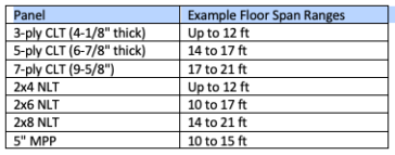
To determine efficient grid spacing, it is important to understand possible span ranges for mass timber floor panels. Due to their relative light weight, allowable spans for these panels are often governed by vibration and deflection rather than bending or shear capacity. In addition to panel vibration design, vibration performance of the framing system as a whole, including beams, should be taken into account. The table below illustrates example ranges based on panel size, assuming stiff supports. (Each project’s specific span, loading and support conditions, as well as manufacturer-specific design properties, should be accounted for when selecting panel thickness.) For more details on the structural design of mass timber floor panels, contact your local WoodWorks Regional Director or email the WoodWorks help desk at help@woodworks.org. For additional information, see the Structure magazine article, Cross-Laminated Timber Structural Floor and Roof Design, and Nail-Laminated Timber: U.S. Design and Construction Guide.
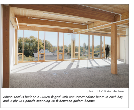
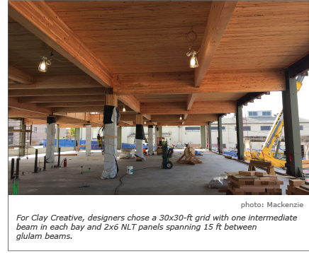
Based on completed buildings in the US, square grids tend to be in the range of 20×20 to 30×30 ft. Although a mass timber panel may be able to span the 20-ft distance between support beams in a 20×20-ft grid, an alternate method would be to include one intermediate beam within each bay to reduce the span of the mass timber floor panel. For example, a 20×20-ft grid could have one intermediate beam so 3-ply CLT floor panels spanning 10 ft can be used. This scenario was used for the Albina Yard office building in Portland, OR (pictured above). Larger square grids such as 28×28 or 30×30 ft with one intermediate beam can also be used. This typically results in the use of 5-ply CLT or 2×6 NLT floor panels, spanning 14 or 15 ft. This scenario was used for Clay Creative, also in Portland (pictured below). In general, thinner floor and roof panels may result in lower material costs. However, lower horizontal panel costs may be offset by higher beam (and perhaps column) costs, and additional intermediate beams also need to be coordinated with MEP systems. As such, a cost analysis for thicker floors and fewer beams vs. thinner floors and more beams may be necessary.
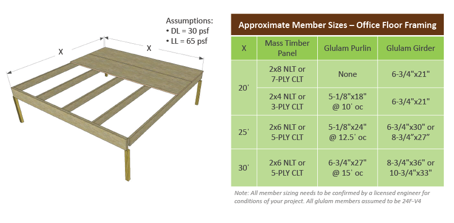
Going much beyond a 30 or 32-ft span with glulam girders starts to require fairly large (deep) beams. It can be done, but economics and headroom issues may outweigh the benefits of longer spans. The image below illustrates several square grid options and associated member sizes.
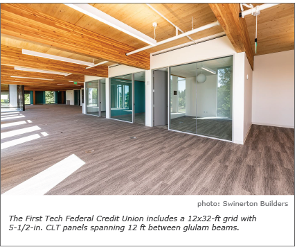
Rectangular grids are usually in the 12×20-ft to 20×32-ft range. The main difference with a rectangular grid is that intermediate beams tend not to be used, often simplifying the approach to accommodating MEP. The narrower grid dimension is typically based on the span capability of the floor panel (see table of span ranges above). The larger grid dimension is based primarily on programmatic layout, while taking into account economical spans for glulam. Projects that have used this scenario include the First Tech Federal Credit Union in Hillsboro, OR, which used a 12×32-ft grid with 5-1/2-in. CLT panels spanning 12 ft, and the 111 East Grand Office in Des Moines, IA, which used a 20×25-ft grid with 2×8-ft DLT panels spanning 20 ft. Both projects are pictured below.
There are several reasons to eliminate the intermediate beam, but the one often cited by design teams is easier MEP coordination. Since exposing the mass timber floor panels on the ceiling side is desired in most mass timber buildings, some creativity in how ductwork, sprinkler lines and other MEP services are accommodated is required. For more information on this topic, read this WoodWorks Ask an Expert Q&A. If there are no intermediate beams, the main MEP trunk lines can be run around a central corridor with branch lines extending into each bay. A benefit to this approach is that no intermediate beams means no or minimal penetrations through glulam purlins or girders to coordinate, cut, design for, etc.
Manufacturer Input
When selecting grid dimensions, another important consideration is manufacturer capabilities. Most North American CLT manufacturers certified to the PRG-320 Standard for Performance-Rated Cross-Laminated Timber are capable of producing panels between 8 and 12 ft wide and between 40 and 60 ft long. Minimizing the amount of waste from each panel is key to maximizing efficiency. For example, a grid with 20-ft increments could be very efficient; it could use 40-ft-long panels or 60-ft-long panels (if the manufacturer is capable of producing those sizes). On the other hand, a 24-ft grid may not be as efficient since it would either require 48-ft-long panels (for double spans) or cutting 16 ft from 40-ft-long panels. Both options increase waste and reduce efficiency. When considering especially long panels, trucking logistics should also be taken into account.
The University of Arkansas Adohi Hall student residence hall project in Fayetteville, AR utilized a 20-ft grid increment for a 60-ft-wide building. The CLT manufacturer provided 40-ft-long panels, resulting in the use of one full length and one half-length panel to achieve the full 60-ft building width. Because each half-length panel was simply a full-length panel cut in half, efficiency was high and waste was minimized.
While manufacturer capabilities differ, it is possible to create grids that are efficient for several manufacturers. An important step in mass timber building design is to consult with manufacturers to determine the most efficient panel layouts for their capabilities. Most North American mass timber manufacturers are WoodWorks National Partners. Information on each can be found by clicking the logos on this webpage.