Expert Tips
Seismic Design of Wood Over Podium Projects
Key topics for engineers analyzing podium projects under lateral loading, including two-stage seismic analysis and diaphragm flexibility.
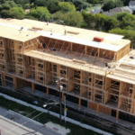
With an increase in podium style buildings—which commonly include four or five stories of wood-frame construction over a one- or two-story concrete podium—has come a need for greater understanding of seismic design considerations associated with these types of framing systems. Two items in particular often arise when analyzing these buildings under lateral loading: the inherent differences in lateral-resistance properties of the building above vs. the podium below, and a growing tendency to provide less lateral-resisting elements around the perimeter of the building above the podium, limiting the options for shear walls.
The 2015 International Building Code (IBC) allows a maximum building height above grade of 75 feet using Type IIIB construction and 85 feet for Type IIIA if NFPA 13 sprinklers are used. However, it only allows up to five stories for Types IIIA or IIIB structures under those same conditions. Structural provisions in the American Society of Civil Engineers’ Minimum Design Loads for Buildings and Other Structures (ASCE 7) limit the maximum height of wood structural panel-sheathed shear walls to 65 feet above the base of the seismic force-resisting system (SFRS) in Seismic Design Categories (SDC) D, E, or F. In order to gain additional stories, increase building area, and stay within the allowable building and seismic system heights, the IBC and ASCE 7 each have provisions which enable podium designs.
Two-Stage Seismic Analysis
Structurally, ASCE 7-10 Section 12.2.3.2 provides a two-stage analysis procedure that can be beneficial for seismic design of podium projects. The procedure treats the flexible upper and rigid lower portions of the structure as two distinct structures, thereby simplifying the seismic design process. Only the weight of the flexible upper portion has to be considered in its design, not the entire weight of both portions. The two-stage analysis also allows the seismic base of the upper portion to be the top of the lower portion. This allows measuring the maximum SFRS height for a wood structural panel-sheathed shear wall system, in SDC D through F of 65 feet, from the top of the podium. The requirements for a two-stage analysis are:
- The stiffness of the lower section is ten times the stiffness of the upper section.
- The period of the entire structure is not more than 1.1 times the period of the upper portion considered as a separate structure supported at the transition from the upper to lower portions.
- The upper portion is designed as a separate structure using the appropriate R and redundancy factor, ρ.
- The lower portion is designed as a separate structure using the appropriate R and ρ. The reactions from the upper portion are determined from the analysis of the upper portion amplified by the ratio of the R/ρ of the upper portion over the R/ρ of the lower portion. This ratio is not less than 1.0.
- The upper portion is analyzed with the equivalent lateral force or modal response spectrum procedure, and the lower portion is analyzed with the equivalent lateral force procedure.
Some confusion exists regarding the required amplification of forces that are transferred from the flexible upper portion into the podium slab. The amplification factor in ASCE 7-10 Section 12.2.3.2 (d), when used, applies to only the seismic component of the reaction forces, not the entire reaction-included gravity loads. Gravity framing (e.g., beam, post-tensioned slabs, columns) supporting a discontinuous shear wall is designed for over-strength where required by ASCE 7-10 Section 12.3.3.3. Connection requirements to the podium slab are shown in the figure below.

Diaphragm Flexibility
Distribution of forces to the vertical resisting elements are based on analysis methods where the diaphragm is modeled as either idealized as flexible, idealized as rigid or modeled as semi-rigid. Current practice for light-frame construction commonly assumes that wood diaphragms are flexible for the purpose of distributing horizontal forces to shear walls. ASCE 7-10 Section 12.3.1.1 (c) allows diaphragms in light-frame structures to be idealized as flexible when 1-1⁄2 inches or less of non-structural topping, such as concrete or a similar material, is placed over WSP diaphragms, and each line of vertical elements of the seismic force resisting system complies with the allowable story drift of ASCE 7-10 Table 12.12-1. Using the flexible diaphragm assumption would allow distribution of diaphragm forces to shear walls based on tributary area. In contrast, a rigid diaphragm analysis distributes diaphragm forces to shear walls based on the relative stiffness of the shear walls.
Even though diaphragms may be idealized as flexible, it is sometimes good engineering judgment to consider other flexibility conditions. Currently, some designers only perform a flexible diaphragm analysis and some a rigid diaphragm analysis, but a few use semi-rigid modeling (enveloping). On that basis, some confusion and lack of consistency exist regarding which type of diaphragm analysis should be employed for a given project. Verifying the diaphragm flexibility is becoming increasingly more important given trends toward larger openings in exterior shear walls, shorter wall lengths, and a greater number of wood-frame stories over the podium.
For more information on this topic, see this Structure magazine article from January 2017.


