Expert Tips
Alignment of Bearing Wall Studs and Trusses/Joists in Multi-Story Wood Construction: Structural Design Considerations
Design and detailing considerations for wall framing when trusses, joists and rafters don’t align with studs in mid-rise light-frame wood buildings.

With the proliferation of mid-rise wood construction across the country, one of the more hotly debated topics among engineers and contractors is whether bearing wall stud and floor or roof truss/joist alignment is required for the full height of a building. Fundamentally, there are two decisions to make: should bearing wall studs align from floor to floor, and should floor/roof trusses, joists and rafters align with wall studs. To make these decisions, one must first answer the following:
- How many stories or levels does the project have?
- What is the magnitude of truss/joist/rafter reaction?
- Is there a full-depth rim board and, if so, what is its width? Is it a solid sawn wood product or engineered wood product?
- Is there a ribbon board at the top of the floor truss?
- Are the wall top plates traditional double 2x or something different?
- What is the stud spacing?
- What is the truss/rafter/joist spacing?
From a constructability standpoint, allowing misalignment of studs and joists/trusses might be preferred as alignment requires a higher level of planning and execution by the contractor. Misalignment of studs from one level to the next can also result in more efficient designs since stud spacing can be optimized on any given level to accommodate accumulated loads.
However, one positive aspect of floor-to-floor stud alignment is that plumbing stacks can run vertically for the height of the building without interfering with studs.
Misalignment of Studs and Trusses/Joists
One method of allowing misalignment of studs from one level to the next is utilization of full-depth rim boards. In this scenario, the stud above transfers loads to the bottom plate of the wall, through the floor sheathing and into the rim board. The rim board can then distribute loads to the top plate below, which transfers loads to the misaligned studs. As is often the case with wood stud wall design for axial loads, the limiting design criteria can be perpendicular-to-grain loading and capacity of the plates, rather than axial and buckling capacity of the studs. In lieu of a full-depth rim board, a rim girder truss can be evaluated as an option.
Regardless of whether the studs align from one floor to the next, the reactions of the floor/roof trusses/joists must also have a load path to the studs below. In most situations, the trusses/joists bear on the double 2x top plates of the wall assembly below. The most direct load path would be to always align a stud (or studs if necessary) directly below each truss/joist. However, this may be undesirable from a design standpoint—e.g., when wall studs are at 16-in. o.c. to accommodate minimum spacing for exterior finishes while floor joists are at 24-in. o.c. to maximize floor sheathing capacity. In this case, the wall plates may have the capacity to span between studs that do not align with the joists/trusses. If the double plate does not have sufficient capacity to support the reaction of the truss/joist, it is possible to support the truss/joist on the full depth rim board/girder truss first, and then distribute loads to the top plates via the rim board/girder truss. The cost of the fasteners required to achieve this load path should be considered.
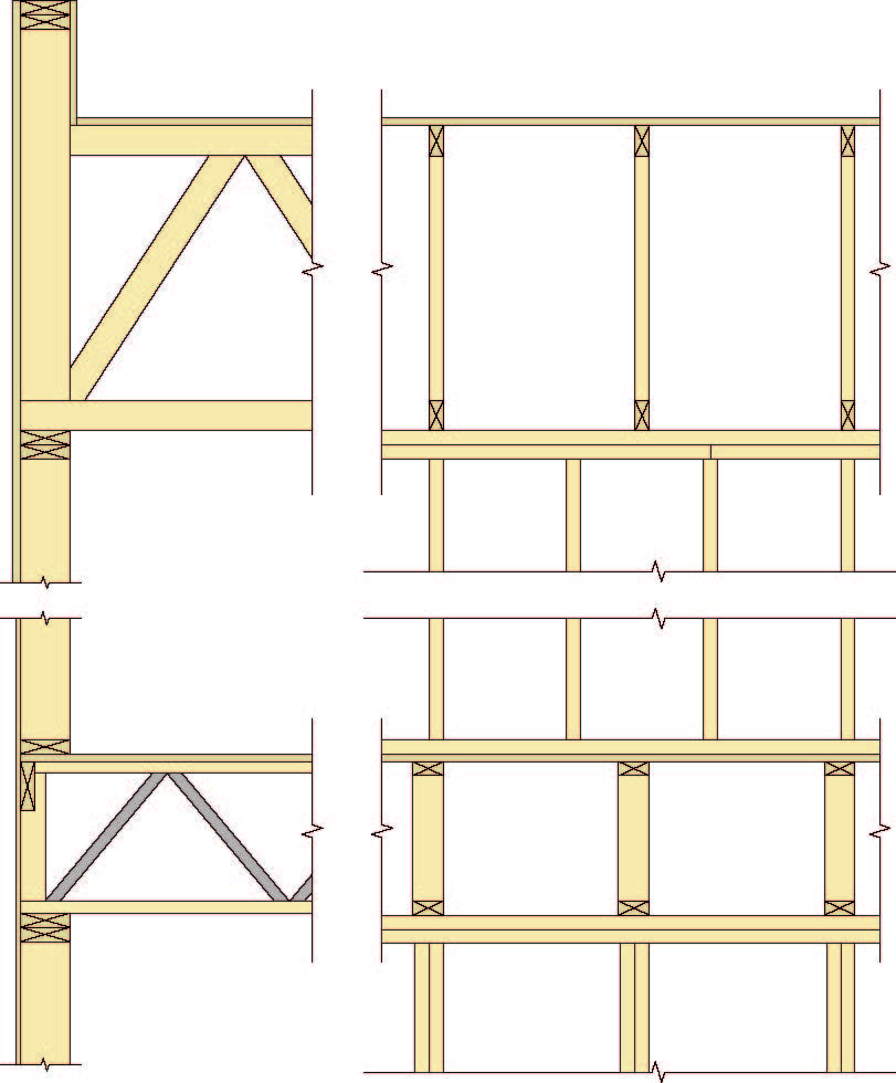
With parallel chord trusses, a common approach is to use a ribbon board at the top of the floor truss system. The ribbon board, often a 2×4 or 2×6 oriented vertically, flush top with the top of the trusses, can be designed to collect loads from the studs above and transfer them directly to the end of the attached floor trusses. If the double top plate below the floor truss system is structurally adequate to support the reaction of the floor trusses (spanning between misaligned studs below if necessary), then nothing further is needed. If the double top plate is not structurally adequate to support the truss reactions, then another ribbon board can be placed flush bottom with the trusses to redistribute the loads to the plates and studs below. Alternatively, the studs below the trusses could be made to align with the trusses.
Design Process for Bearing Wall Top Plates
As noted above, the double 2x top plates in a conventional wall framing system are often required to transfer loads and are therefore a critical piece in the wall design process. In many scenarios, the wall double top plates need to act as structurally-spanning members, resisting concentrated loads (truss/joist reactions) at the middle of a stud bay, near the end of a stud bay, or anywhere in between.
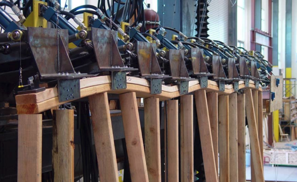
Photo: Dan Dolan
When considering how to address this issue, there are several variables at play, such as:
- If using typical double plate construction with staggered joints, do both plates act together as a composite member and, if so, does adequate nailing between the two need to be provided for shear flow?
- If the plates are assumed to act independent of each other, what is the load distribution between them? Does the top plate take as much load as it can and the bottom plate take the rest? Is the load evenly split between the two plates?
- What justification is there for this load transfer between plates (regardless of what magnitude is transferred)? Is equal deflection/stiffness of the two plates assumed? Is direct bearing of the top plate on the bottom plate considered adequate for load transfer? Is load transfer between the two plates different when looking at moment vs. shear?
- Should this analysis assume both plates are simple span for one stud bay, should one of the plates be assumed continuous for several adjacent bays, or should both plates be continuous for several bays?
- Will the wall gypsum or wood structural panel sheathing contribute to resisting the vertical forces acting on the top plate?
This condition is not specifically addressed in the International Building Code, National Design Specification® (NDS®) for Wood Construction, or other codes or referenced standards. There are also multiple methods of conducting this analysis, which can produce significantly different results.
The least conservative analysis is to assume the two plates are acting together as one composite, 3-in.-deep member for both shear and bending. Although some engineers use this method, it can be unconservative since nailed connections in wood members are relatively flexible and the typical nailing pattern between the two plates is not close to being adequate to make them act compositely due to nail slip. The textbook shear flow equations don’t work well for light-frame wood construction since they are based on rigid connections (such as a built-up steel I-shapes with welded connections). This makes achieving adequate shear flow transfer between the two wood plates unreasonable.
The general consensus is to assume the two plates act independently with the load distributed to each plate based on deflection/stiffness. In other words, for common top plate construction, half the load goes to each plate.
As far as splice locations and looking at continuous vs. simple-span members, there should be some offset in top plate splices to provide continuity in at least one top plate member. One approach is to envelop the worst-case scenario of both analyses. A simple span will produce the worst bending effects and a continuous span will produce the worst shear effects.
The downside of using this analysis method is that the capacity of the plates is low. A double 2×6 spruce-pine-fir top plate with studs at 16-in. o.c. has a truss reaction capacity of approximately 1,000 to 1,400 lbs. depending on load location. The American Wood Council’s Wood Frame Construction Manual (WFCM) prescriptively limits floor joist spans to 26 ft to address this issue. WFCM commentary to Section 3.1.3.2a states the following:
C3.1.3.2a Framing Member Spans. Framing member spans are limited to 26 feet for floors based on the bending capacity of the double top plate supporting floor framing members. The worst-case assumption is that a floor framing member bears directly between two studs creating a concentrated load at mid-span of the top plates. Section 3.1.3.3g required band joists, blocking, or other methods to transfer roof, wall, and/or floor loads from upper stories to alleviate the concern of additional loads being transferred through the floor framing members into the top plate.
If the method mentioned above is used, any moderate to long-span trusses will have reactions requiring top plate reinforcing or adjustments in stud/truss spacing. This is certainly not to say that other analysis methods like utilizing fastening of wood sheathing to the top plate, which produce larger plate capacities, can’t be used. However, justification for using those methods may be more difficult to achieve.
Options for achieving larger plate capacities at the spacing transition include using a solid 3x or 4x plate, using a triple 2x top plate, adjusting stud or truss spacing to make the elements align, adding studs under trusses that don’t align with typical stud layout, or using a higher strength/grade or engineered wood top plate. If a triple top plate is used, a repetitive member factor of 1.15 could be used. Recall that the repetitive member factor only applies to the bending capacity and the plate capacity is frequently governed by shear capacity.
Conclusions and Recommendations
As light wood framing continues to be used on larger and more complex structures, engineering challenges such as misalignment of studs and joists/trusses will need to be addressed. Other factors, such as the desire to increase wall insulation, will have an impact on engineering decisions, as will material costs and constructability.
The capacity of a conventional double 2x top plate is often overlooked when designing multi-story light-frame projects. The design process for bearing walls, as well as the floor-to-wall intersection details, should consider whether alignment of studs from one level to the next, and alignment of studs with trusses/joists, are required or not.
This article includes information provided by Schaefer based on project-specific scenarios.