Expert Tips
Detailing Floor-to-Exterior Wall Conditions in Type III Projects
Discusses common questions not clearly answered in the IBC, clarifying language added to the 2024 edition and providing example strategies and additional resources
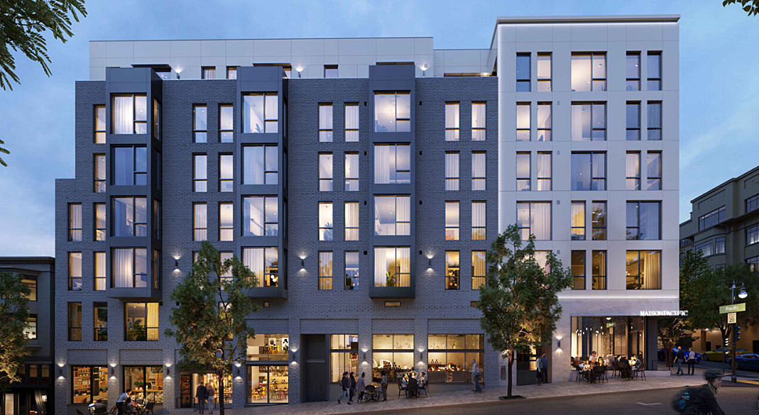
Maison Pacific / JS Sullivan / RG Architecture / Photo IMEG
This article references the 2024 International Building Code (IBC).
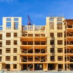
Type III construction is typically used for five-story wood-frame residential projects, with or without a podium, and may also be used for six-story wood-frame office buildings. When designing these buildings, code requirements for wall and floor detailing come from many parts of the IBC.
Exterior walls in Type III construction are required to be framed with non-combustible materials or fire-retardant-treated wood (FRTW), while the floor and roof framing can be standard, untreated wood framing.
In terms of fire-resistance ratings (FRRs), exterior bearing walls must meet the more stringent requirement of IBC Table 601 and Table 705.5, meaning the required FRR is governed by the worst-case condition of these tables. Exterior non-load-bearing walls, however, are governed only by the fire separation distance requirements in Table 705.5. For occupancies other than Group H, a typical load-bearing exterior wall in Type III construction must have a 2-hour FRR (Table 601). Per Table 705.5, non-load-bearing exterior walls require a 1-hour FRR if the fire separation distance is 5 feet or more and can potentially be unrated (0-hour) if the fire separation distance is at least 30 feet. A metal or wood stud wall is defined as load bearing if it supports more than 100 pounds per linear foot of vertical load in addition to its own weight. Learn more about load-bearing wall assessment and design in the WoodWorks article, How to Determine if Exterior Walls are Load or Non-Load Bearing and Why That’s Important.
Floor framing assemblies in Type III buildings can vary based on the construction subtype, with Type III-A requiring a 1-hour FRR and Type III-B requiring no rating (Table 601). However, other provisions of the code may require additional fire resistance based on the occupancy. For example, residential occupancies require a 30-minute or 1-hour rating for the floor construction (Table 601, Sections 420.3 and 711.2.4.3).
As noted, code requirements for exterior wall and floor detailing come from many parts of the IBC. For many multi-family projects this results in a 2-hour-rated, FRTW exterior wall and a 1-hour-rated, untreated wood floor assembly. The remainder of this article will focus on this common scenario.
The intersection of these 1-hour and 2-hour assemblies raises questions about fire resistance and material continuity that were not historically addressed in the IBC:
- What fire-resistance continuity requirements exist? Unlike provisions listed for fire-resistance continuity of fire walls, fire barriers, and fire partitions, the IBC did not specify continuity requirements for exterior walls prior to the 2024 IBC.
- What material requirements exist where a wood floor assembly intersects and supports an exterior wall above? Again, the IBC did not historically contain language specific to continuity requirements of exterior walls prior to the 2024 IBC.
A challenge for building design and construction professionals is that there has been a significant variety in what is considered acceptable from one building jurisdiction to another. The 2024 IBC has implemented additional language specific to the intersection of floor and exterior wall design within two specific sections:
IBC 705.6 – Continuity
This addition to the 2024 code addresses continuity of the FRR for exterior walls, stating that the rating must be continuous from the top of the foundation or floor/ceiling assembly below to one of the following:
- The underside of the floor sheathing, roof sheathing, deck or slab above
- The underside of a floor/ceiling or roof/ceiling assembly having a fire-resistance rating equal to or greater than that of the exterior wall and the fire separation distance exceeds 10 feet.
For most multi-family projects that include a 2-hour fire-resistance-rated exterior wall and a 1-hour fire-resistance-rated floor system, the code now specifies that the FRR of the wall must be continuous to the underside of the floor or roof sheathing above. For the example of a 1-hour-rated floor intersecting a 2-hour-rated exterior wall, one option is to utilize semi-ballon framing, ensuring the wall assembly is continuous to the underside of the floor or roof sheathing; however, this often requires the gypsum on the interior face to run continuous to the top of the plates, which can create complications with floor assembly components penetrating the gypsum membrane.
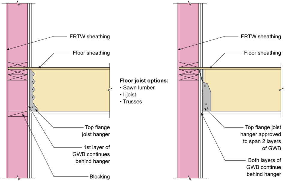
FIGURE 1: Two common assemblies of a semi-balloon-framed exterior wall/floor intersection with continuous wall membrane to underside of floor sheathing above
It is important to note that the fire-resistance continuity of the wall does not necessarily require the specific wall assembly to be continuous to the underside of the floor or roof, such as with a semi-balloon framed wall (Figure 1). Instead, continuity can be maintained with wood blocking (including structural composite materials), rim board, gypsum, or sheathing to meet the required fire resistance of the wall per IBC Table 601. This is common to platform framing (Figure 2) and calculation of the FRR is discussed below.
IBC 705.7.1 – Floor Assemblies in Type III Construction
This 2024 addition addresses the question of material and FRR requirements for floor elements that support exterior walls by clarifying the following:
- Floor assembly building elements within the plane of the exterior wall, including rim joists, rim boards, and blocking, do not have to be noncombustible or FRTW. They can be untreated wood or any other material allowed by code, in accordance with interior building elements of Type III construction (Section 602.3).
- The FRR for the portion of the floor assembly that supports the exterior wall (e.g., rim boards) shall not be less than the FRR of the exterior wall being supported. Clarifying language within Section 705.7.1 includes the contribution of the ceiling membrane toward the required minimum FRR of the floor/ceiling assembly elements.
To help address implementation of the new language within the design and construction community, a committee of experts from the American Wood Council (AWC), WoodWorks, and partner organizations investigated code requirements and testing completed for the floor-to-exterior wall configuration. Detailing strategies were developed that are both “framer friendly” and meet IBC requirements. The strategies and their rationale are included in the 2024 update of AWC’s DCA 3 – Fire-Resistance-Rated Wood-Frame Wall and Floor/Ceiling Assemblies, including fire-resistance times for rim board. (See Figures 1A, 1B, 1C, and 2 in DCA 3.)
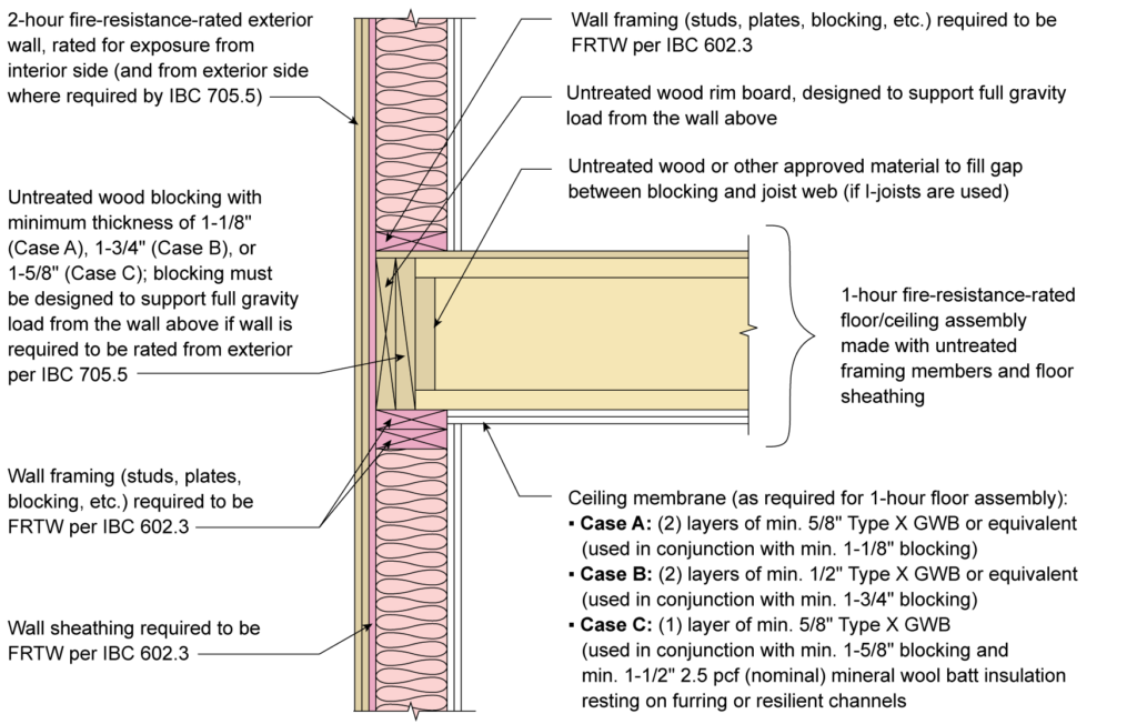
FIGURE 2: Example detail for Type III-A exterior wall-floor intersection with rim board and blocking
Source: DCA 3 Figure 1A, AWC
Figure 2 above (Figure 1A in DCA 3) shows an example detail and rationale for how a 1-hour fire-resistance-rated floor assembly with ceiling membrane of Type X or Type C gypsum wall board can be platform-framed on a 2-hour fire-resistance-rated wall. The required 2 hours of protection from within the room through the exterior wall is provided by a combination of the ceiling membrane, wood blocking (in the depth of the floor), and a rim board at the end of the floor framing in the plane of the exterior wall. DCA 3 also notes that neither the blocking in the wall, floor framing, nor floor sheathing that penetrates the exterior wall needs to be FRTW as these are considered floor assembly elements, not part of the exterior wall. IBC only requires that exterior wall framing and sheathing be FRTW.
For a typical joist system (sawn lumber or I-Joists), blocking between the joists to maintain fire-resistance continuity of the wall support is relatively easy to achieve, especially with 2×6 framed walls, which allow multiple pieces of blocking or rim board to meet the necessary FRR.
For project-specific assistance, including the use of plated wood floor trusses, contact your local WoodWorks Regional Director.