Expert Tips
Classifying Wood Diaphragms as Flexible or Rigid
Using rigid diaphragm analysis can help accommodate complex building geometries

This article references the 2024 IBC, 2021 SDPWS, and ASCE 7-22.
The type of diaphragm rigidity used in a building design can have a significant effect on how lateral forces are distributed to vertical lateral force-resisting elements and the overall efficiency of the structural design. Although flexible diaphragms tend to be the default analysis approach for light-frame wood structures, rigid diaphragm analysis is becoming more common due to increasingly complex building designs.
Diaphragm rigidity is addressed in the 2024 IBC Section 1604.4, which, in part, states:
“…Where a diaphragm is not permitted to be idealized as either flexible or rigid in accordance with ASCE 7 or for wood diaphragms in accordance with AWC SDPWS, the structure shall be analyzed and designed utilizing one of the following procedures:
- An envelope analysis of the structure using a flexible and rigid diaphragm analysis separately and designing each component for the more severe load condition.
- A semirigid diaphragm analysis and design.”
Notably, it refers to American Wood Council’s Special Design Provisions for Wind and Seismic (SDPWS) for determining whether a diaphragm can be idealized as flexible or rigid.
Flexible Diaphragms
SDPWS Section 4.1.7.1 defers to ASCE 7 when it comes to classifying a diaphragm as flexible. ASCE 7 has different classification criteria depending on the loading the diaphragm is subjected to (i.e. wind or seismic).
For wind design, ASCE 7 permits all diaphragms constructed with wood structural panel sheathing (e.g., plywood or OSB) to be prescriptively idealized as flexible, per the definition of “Diaphragm” in Section 26.2.
For seismic design, ASCE 7 Section 12.3.1.1 permits diaphragms sheathed with wood structural panels and no more than 1 ½” of nonstructural concrete or similar topping to be prescriptively idealized as flexible, provided each line of vertical resistance meets the ASCE 7 story drift limits under seismic loading. If these conditions are not met, ASCE 7 Section 12.3.1.3 provides a method by which a diaphragm can be idealized as flexible by calculation—when the maximum simple-span diaphragm deflection (ẟMDD) is greater than 2 times the average story drift at the adjacent supporting walls (ΔADVE).
ẟMDD > 2 * ΔADVE
Rigid Diaphragms
SDPWS Section 4.1.7.2 uses the inverse equation, noting that a simple span diaphragm can be idealized as rigid when:
ẟMDD ≤ 2 * ΔADVE
SDPWS also provides guidance on how to perform this check for a cantilevered diaphragm.
Semi-Rigid Diaphragms
As noted in IBC Section 1604.4, if none of the prescriptive or calculated methods for idealizing the diaphragm as flexible or rigid are met, or if the designer feels that a flexible or rigid classification is not appropriate, the diaphragm must be designed using a semi-rigid diaphragm analysis or an envelope method, where the system is analyzed using both flexible and rigid diaphragm assumptions to capture the worst-case demands. An envelope analysis tends to be a simpler approach than a semi-rigid analysis because of the significant effort to perform an accurate semi-rigid analysis in commercial structural analysis programs.
To assist readers with diaphragm classification, Figure 1 below provides a simple flow chart for diaphragms subject to seismic loads. It is also rational to use this for wind loads.
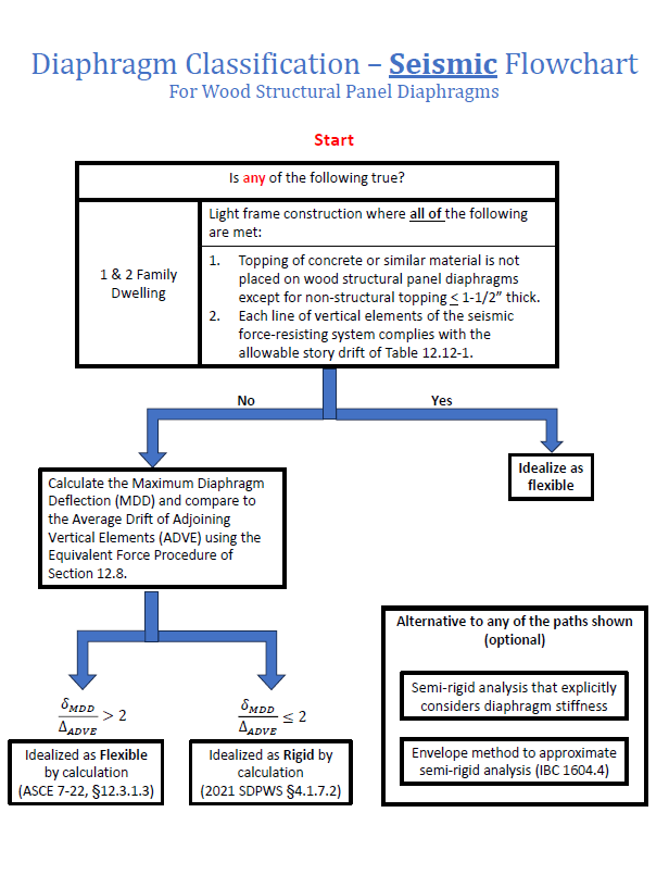
Click here to view a full size version of Figure 1
Flexible vs Rigid Diaphragms in Previous IBC Editions
The 2021 and earlier editions of the IBC had the following language regarding diaphragms:
“…A diaphragm is rigid for the purpose of distribution of story shear and torsional moment when the lateral deformation of the diaphragm is less than or equal to two times the average story drift.”
IBC 2024 removed this general provision to determine the diaphragm as rigid by calculation, but added the reference to the SDPWS, which contains the same criteria. While this change doesn’t change wood diaphragm design practice, it does provide a clear code path for designers by incorporating references to SDPWS and ASCE 7.
Determining an Appropriate Method:
Today’s design trends often result in more frequent, larger openings, and more complex structural configurations. This creates scenarios where there may be cantilevered diaphragms and/or significant stiffness discrepancies between shear wall lines.
Figure 2 shows a hypothetical floor plan where, in the long direction, there is little shear wall length available on the exterior walls compared to the corridor walls.
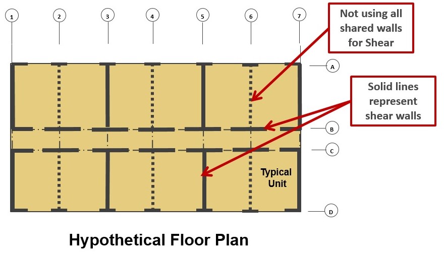
Looking at loading in the longitudinal direction for this layout and utilizing a flexible diaphragm classification, Figure 3 illustrates what that force distribution looks like based on tributary area to each line of lateral force resistance.
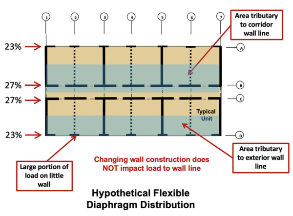
Here, similar loads are resisted by both the interior and exterior wall lines, but the exterior wall line has only one third of the available wall length. Thus, the demand on a pound-per-foot basis will be nearly three times higher at the exterior line. If the shear walls at the exterior line are governed by story drift limits, the difference in detailing requirements may be even more significant.
Figure 4 below shows a hypothetical redistribution of the load to the shear wall lines using a rigid diaphragm analysis. Here, lateral loads are distributed to the shear wall system proportional to the relative stiffness of each wall in the building, and not through simple tributary area distribution. The rigid diaphragm design approach does require more calculations, typically using a spreadsheet analysis of each floor level. Performing hand calculations of this is not typically practical.
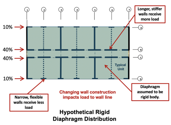
Note, with shorter, more flexible shear walls on the exterior and longer, stiffer shear walls along the corridor, the rigid diaphragm analysis distributes a smaller portion of the lateral load to the exterior shear wall line. By transferring more of the demand to the wall segments at the corridor, this can relieve the shear and overturning demands at the exterior wall segments when compared to the flexible diaphragm classification. However, in some instances, especially in multi-story light frame structures, the demand is still too high for those short exterior wall segments, and a cantilever diaphragm approach needs to be explored as shown in Figure 5 below.
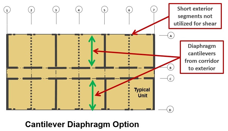
For a detailed design example on cantilevered diaphragms, readers are encouraged to download WoodWorks’s Design Example of a Cantilevered Wood Diaphragm.
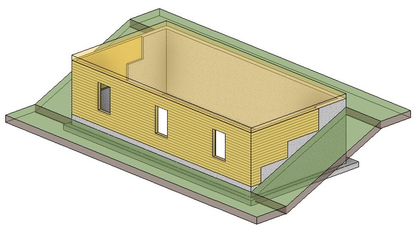
Diaphragms in Hillside Light-Frame Structures
New to the 2022 edition of ASCE 7 for seismic loads is section 12.3.1.4, which provides requirements for diaphragms in hillside structures. This typically occurs when a retaining structure (concrete or masonry walls) laterally braces one or more sides of the diaphragm with the other side(s) being braced by light-frame wood walls. When the hillside criteria of ASCE 7 section 12.3.1.4 are met, the wood framed diaphragm shall be classified as rigid or semi-rigid. Requiring the use of a rigid or semi-rigid analysis ensures the design explicitly accounts for the significant stiffness differences in typical foundation walls and light-frame wood walls. ASCE 7 commentary on this section provides additional language on this section and why it needs to be applied. The isometric view shown in Figure 6 below highlights this condition for the first floor diaphragm (walls above are omitted for clarity). The forces in either direction will follow the stiffest load path, which is usually to the anchorage of the uphill foundation wall(s).