Expert Tips
Classifying Wood-Sheathed Diaphragms as Flexible or Rigid
While flexible diaphragms are common, it can be beneficial to justify that a wood diaphragm is rigid in buildings with certain characteristics, such as cantilevered diaphragms or wall lines of significantly different lengths.
Designers engineering buildings with wood diaphragms typically distribute horizontal seismic and wind loads to the shear walls or other lateral-force resisting elements using the tributary area method, by idealizing the diaphragm behavior as flexible.
For wind design, ASCE 7 permits all diaphragms constructed with wood structural panel sheathing (e.g., plywood or OSB) to be automatically idealized as flexible in Section 26.2.
For seismic design, ASCE 7 Section 12.3 permits diaphragms sheathed with wood structural panel and with no more than 1 ½” of non-structural concrete or similar topping to be idealized as flexible, provided each line of vertical resistance meets the ASCE 7 story drift limits to seismic loading. If these conditions for idealization are not met, ASCE 7 Section 12.3.1.3 provides a method by which a diaphragm can be justified to be flexible by calculation—when the maximum simple-span diaphragm deflection (ẟMDD) is greater than 2 times the average story drift at the adjacent supporting walls (ΔADVE).
ẟMDD > 2 * ΔADVE
While flexible diaphragms tend to be the default, there are situations where it is advantageous to justify that a wood diaphragm is rigid. Examples include buildings with significant cantilevered diaphragms and situations where shear wall lines are of significantly different lengths. Given the trend toward more complex structural configurations, it is increasingly common for multi-story mixed-use and multi-family wood buildings to be designed using a rigid diaphragm analysis.
The first figure below shows a hypothetical floor plan where, in the long direction, there is little shear wall length available on the exterior walls compared to the corridor walls.
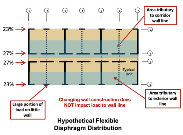
The first figure shows the distribution of lateral loads by the tributary area using the flexible diaphragm approach. Here, similar loads are resisted by both the interior and exterior wall lines. If the exterior line has 1/3 of the wall length available, then the capacity requirements, on a pounds per foot basis, will be nearly three times higher at the exterior line. If the shear walls at the exterior line are drift-governed to meet story drift limits, the difference in detailing requirements may be even larger.
The figure below shows a hypothetical distribution of the load to the shear wall lines using rigid diaphragm analysis (RDA). With RDA, lateral loads are distributed to the shear wall system proportional to the relative stiffness of each wall in the building, and not through the simpler tributary area distribution. The rigid diaphragm design approach does require more calculations, with at least a spreadsheet analysis of the building system. Performing hand calculations of this quickly is untenable.
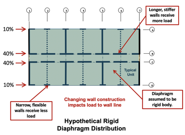
Note how, with shorter shear walls on the exterior relative to the corridor, the rigid diaphragm analysis distributes a lower portion of the lateral load to the exterior shear wall line. This results in similar force demands (plf) on the interior and exterior shear walls and can make some difficult design situations more achievable than with flexible diaphragm analysis.
Justifying a Rigid Diaphragm Analysis
ASCE 7 does not provide a method to idealize a diaphragm as rigid via calculation; however, such conditions are detailed in the International Building Code (IBC) and the American Wood Council’s Special Design Provisions for Wind and Seismic (SDPWS). IBC Section 1604.4 states that a diaphragm is rigid for distribution of story shear and torsional moment when the lateral deformation of the diaphragm is less than or equal to two times the average of the story drift. Similar language is in SDPWS 2015 Section 4.2.5. Reusing the notation from ASCE 7, per IBC Section 1604.4, a simple span diaphragm can be idealized as rigid when:
ẟMDD ≤ 2 * ΔADVE
To justify a wood diaphragm as rigid, the deflection of the diaphragm can be calculated using SDPWS 4.2.2, the deflections of the supporting shear walls can be calculated using SDWPS 4.3.2, and the numbers can be compared using the above checks. If the deflection of the diaphragm is less than two times the deflection of supporting walls, the diaphragm can be idealized as rigid. Depending on the structural configuration, it may be necessary to use a blocked diaphragm to have enough stiffness to qualify as rigid.