Expert Tips
Exterior Walls in Mass Timber Buildings – Part 5: Thermal Enclosure Design
Strategies to optimize the thermal performance potential of mass timber enclosures
For more information on exterior walls in mass timber buildings, see Part 1: Code Requirements and Commonly Used Materials, Part 2: Common Floor-to-Wall Details, Part 3: Cladding Material Allowances, Types, and Support Details, and Part 4: Panelization.
The low thermal conductivity of mass timber compared to materials like concrete and steel provides a unique opportunity to minimize heat loss and enhance energy efficiency in buildings. Effective thermal enclosure design for mass timber buildings involves key design strategies such as creating a continuous thermal control layer, minimizing thermal bridges, and using appropriately placed insulation materials. By focusing on these aspects, designers can optimize the thermal performance of mass timber buildings, resulting in energy-efficient, comfortable, and durable structures.
Heat Transfer Basics
Heat transfer across the building enclosure (e.g., walls, roof, floors, etc.) is caused by the temperature difference between the indoor and outdoor environments. Heat can transfer through typical building materials, especially at thermal bridges. A thermal bridge is any material or component in the assembly with a higher thermal conductivity than the surrounding materials, creating a path for heat to flow more easily (see Figure 1). Design strategies that minimize heat transfer through the enclosure will improve the building’s thermal performance.
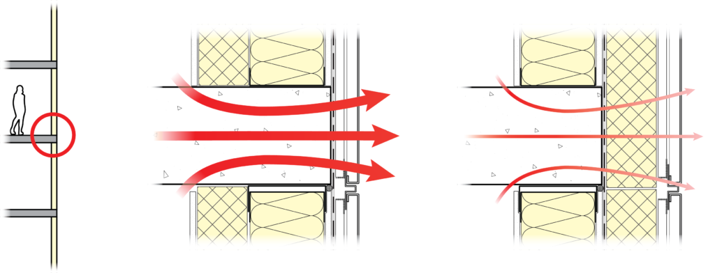
FIGURE 1: An example of a thermal bridge at a floor slab edge (left). The uninsulated concrete slab edge (center) is a significant pathway for heat loss and creates a thermal bridge. The slab edge (right) is insulated to the exterior, allowing for less heat loss and a less significant thermal bridge.
Thermal Control in the Building Enclosure
Most of the heat transfer across the building enclosure is managed by the thermal control layer. A control layer is a stand-alone material or system of materials designed to manage a specific load or loads on a building enclosure.
A well-designed thermal control layer limits heat loss by creating thermal continuity. Thermal continuity is achieved by increasing the continuity of materials that limit heat transfer (e.g., thermal insulation, mass timber, etc.) and reducing the frequency of thermal bridges. A well-designed thermal enclosure will strive for thermal continuity across walls, roofs, floors, windows, and junctions.
Thermal continuity across the building enclosure provides the following benefits:
- Increased enclosure durability and reduced condensation risk. Thermal continuity can maintain warmer temperatures in the enclosure, reducing condensation risks and improving the durability of the assembly components and structure.
- Energy efficiency and operational carbon reductions. Thermal continuity reduces heat loss in winter and heat gain in summer, resulting in lower heating and cooling demands, reduced energy consumption, and the potential to lower operational carbon emissions.
- Thermal comfort for occupants. Thermal continuity can maintain more consistent indoor temperatures.
Thermal Design Considerations for Mass Timber Assemblies
Reducing heat loss across the building enclosure can be achieved with these key design strategies:
- Continuous insulation layers. For buildings in most U.S. and Canadian climate zones, insulation is essential. Most building codes set the minimum required insulation levels but projects with specific performance requirements may require greater levels than those required by code. Like any building, greater insulation continuity will achieve optimal thermal performance for the mass timber enclosure.
Mass timber buildings are typically insulated with continuous exterior insulation. This location provides fewer interruptions in the insulation layer (e.g., at floor and roof edges). Mass timber panels also provide a continuous substrate for cladding attachment systems used with continuous exterior insulation, easing the installation challenges of insulation and cladding. - Low-conductivity (i.e., high thermal-resistance) materials. While dedicated insulation layers and low-conductivity attachments are the primary means of thermal control, mass timber panels also contribute to the assembly’s thermal performance because wood has relatively low thermal conductivity compared to other common structural materials. The wood species influences the thermal resistance of the wood product. Per the 2025 ASHRAE Handbook—Fundamentals, for most North American softwood species, a thermal resistance of R-1.2 per inch (at 12% moisture content) can be assumed for dimensional lumber products. This measure is notably more thermally resistant than other structural materials, such as concrete (R-0.07 per inch) and steel (R-0.04).
- Minimal thermal bridging. Mass timber panels (which provide approximately R-5 or greater) inherently reduce thermal bridges that would be more apparent in steel, concrete, or even light-frame wood construction. The outcome is an opportunity to reduce the amount of exterior continuous insulation. Thermal bridges are also less impactful because the mass timber essentially acts as a significant thermal break. Minimizing the frequency of highly conductive materials through the enclosure (e.g., steel beam penetrations) will further reduce thermal bridging and opportunities for heat loss.
- Thermal mass of mass timber. Mass timber panels can absorb, store, and release heat when exposed to the interior. This heat release moderates indoor temperature fluctuations and creates a more stable indoor thermal environment. The thermal mass of a panel depends on the panel thickness and, minimally, on wood species. The thermal mass of mass timber panels may comply with code-required minimum heat capacity targets, which may reduce a project’s prescriptive insulation requirements. This option allows designers to use slightly less insulation to achieve their performance requirements. The impact of the thermal mass on the design will be determined based on the code interpretations by the authority having jurisdiction.
Wall Assembly Design
The type of insulation and its placement in the enclosure can affect its ability to reduce heat transfer and condensation risks within the enclosure. In mass timber buildings, the insulation is typically located on the exterior of the mass timber, potentially allowing the wood to be left exposed indoors. Exterior insulation keeps the mass timber and its connections inboard of the insulation layer, thereby minimizing thermal bridging. This location also minimizes condensation risk by keeping the wood panel closer to the indoor temperature, limiting temperature and relative humidity fluctuations.
Table 1 discusses insulation considerations for typical mass timber wall assemblies and varying climate zones.
TABLE 1: Wall assembly design guidance for climate zones in the U.S. and Canada
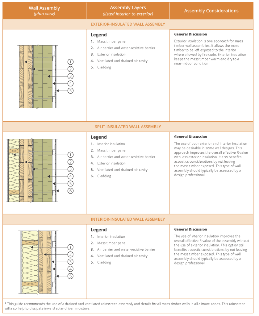
Click the table to view a larger version.
Source: Mass Timber Building Enclosure Best Practice Design Guide V2 by RDH Building Science Inc.
Cladding Attachment
Attachments through insulation, especially those made of highly conductive materials, can reduce the thermal performance of a mass timber enclosure assembly. The more thermally-efficient attachment options consist of lower-conductivity materials, such as stainless steel or fiberglass and/or intermittent attachment systems (clips or fasteners) instead of continuous metal furring.
Table 2 summarizes four common cladding attachment systems for exterior-insulated mass timber wall applications.
Table 2: Common cladding attachment options
Long Screws with Furring Strips
Long screws through exterior insulation are a cost-effective and thermally-efficient option for attaching light- to medium-weight claddings.
With this system, the cladding attaches to treated vertical wood or steel furring strips placed against the face of the exterior insulation. The furring strips fasten back through the insulation to the mass timber panel.
This attachment method offers greater installer convenience for monolithic mass timber backup walls compared to steel stud backup walls—where fasteners must be secured to individual studs—or concrete, which necessitates drilling for fastener placement.
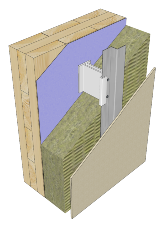
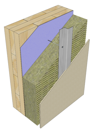
Clip and Rail System
With clip and rail systems, the cladding is attached to vertical or horizontal metal girts.
The girts, or rails, attach to intermittent clips that bridge the insulation and attach to the mass timber structure. The clips may be made of metal (steel, aluminum, stainless steel, or other alloys) or fiberglass or other composite materials. Wood blocks may also be used instead of clips.
The insulation may be rigid or semi-rigid mineral fiber; however, semi-rigid insulation is typically easier to compress and fit around most clip profiles.
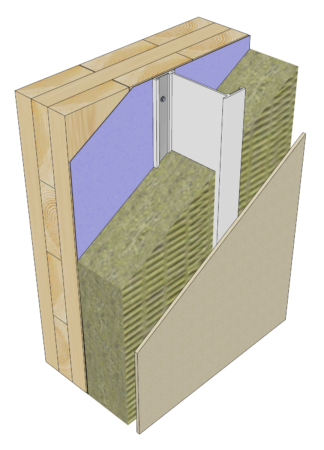
Vertical or Horizontal Girts
Vertically and horizontally-oriented girts are a common form of cladding attachment with rigid or semi-rigid insulation types. Continuous metal girts significantly degrade the performance of exterior insulation, but more thermally-efficient girts made of less thermally-conductive materials such as fiberglass are available.
Horizontal girts may be shimmed to provide a continuous drainage plane at the face of the water-resistive barrier and to seal around girt fastener penetrations through the membrane. Rigid or semi-rigid insulation types can be used with this attachment approach.
For more information on attachment systems, refer to the RDH Building Science guide, Cladding Attachment Solutions for Exterior-Insulated Commercial Walls.
Roof Assembly Design
The thermal design of low-sloped mass timber roof assemblies is generally similar to other common building structure types. However, wood is a hygroscopic material and sensitive to moisture; therefore, it requires more thoughtful moisture management to improve long-term durability and performance.
Table 3 summarizes design guidance for mass timber roof assemblies, including U.S. and Canadian climate zone-specific considerations. The assembly diagrams in the table depict a nail-laminated timber (NLT) structure, but this guidance also applies to other types of mass timber.
As shown in Table 3, the slope of the low-sloped roof membrane may be achieved with sloped over-framing or tapered insulation, or by sloping the structure. These options have a negligible effect on the thermal performance of the assembly and allow moisture to drain during the construction phase; therefore, they are an essential design decision.
Note: Where mass timber assemblies use low vapor-permeance materials, the mass timber panels need to be dry (with a moisture content below 16%) before these materials are installed to prevent trapping moisture within the panels. Low vapor-permeance materials include roofing, waterproofing membranes, rigid foam plastic insulation, and concrete toppings.
For more detailed information about thermal control in mass timber roof assemblies, refer to Mass Timber Building Enclosure Best Practice Design Guide V2.
TABLE 3: Roof assembly design guidance for climate zones in the U.S. and Canada
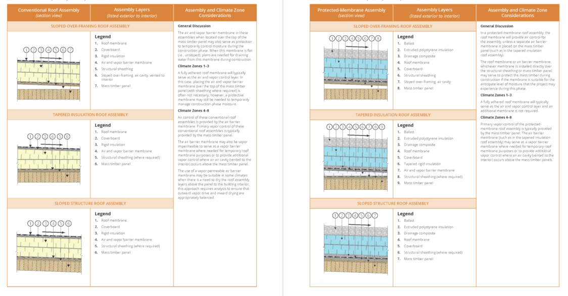
Click the table to view a larger version.
Source: Mass Timber Building Enclosure Best Practice Design Guide V2, by RDH Building Science Inc.
Detailing for Common Thermal Bridges
Since insulation is typically placed exterior of the mass timber enclosure elements, thermal bridges within the field of the roof and wall are usually limited to the attachments necessary to transfer wind and cladding loads back to the structure.
Common thermal bridges through exterior-insulated mass timber wall assemblies include cladding attachments, metal flashings, balcony and canopy connections, beams, and other elements that penetrate through the insulation. At roof assemblies, the most common thermal bridges are due to mechanical attachment of the roofing layers, anchors, or other structural supports, and parapets.
Table 4 shows examples of common areas of thermal bridging and how to reduce these instances on mass timber projects.
For more detailed information about strategies to minimize thermal bridges, refer to Mass Timber Building Enclosure Best Practice Design Guide V2.
Table 4: Common thermal bridges
Thermally Broken Flashing
Thermal bridging that can occur through exterior insulation at sheet-metal flashing penetrations can be reduced in two ways: by fastening the sheet-metal flashing to the cladding attachment or furring system instead of through the insulation, or by using low-conductivity cross-cavity flashing materials like a self-adhered membrane, or silicone/EPDM rubber sheet (see image at left).
When exterior insulation is present, the cross-cavity flashing concept is achieved by cutting the insulation at a slope, extending a flexible flashing membrane over the insulation, and overlapping a non-visible portion of the sheet-metal flashing. A self-adhered flashing membrane used in this way is sometimes called “thermally broken flashing” and is concealed when the enclosure is complete.
Balconies and Canopies
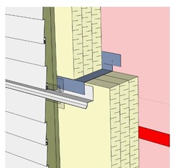
Thermal bridging at balconies and canopies can be significant, especially if continuous structures or connections (made of concrete or steel) are used.
To reduce this thermal bridge across the enclosure plane, project teams may consider intermittent steel connections (stainless steel for improved thermal performance) that allow for adjustment to accommodate construction tolerances. Alternatively, projecting the mass timber through the enclosure plane can provide a structural projection (see image at left), though with greater disruption to the exterior insulation than an intermittent attachment approach.
As a reminder, the mass timber projection must still be designed appropriately to manage moisture and air leakage for long-term durability. Guardrail connections, perimeter edge and saddle detailing are particularly important to detail properly to keep the projecting wood dry.
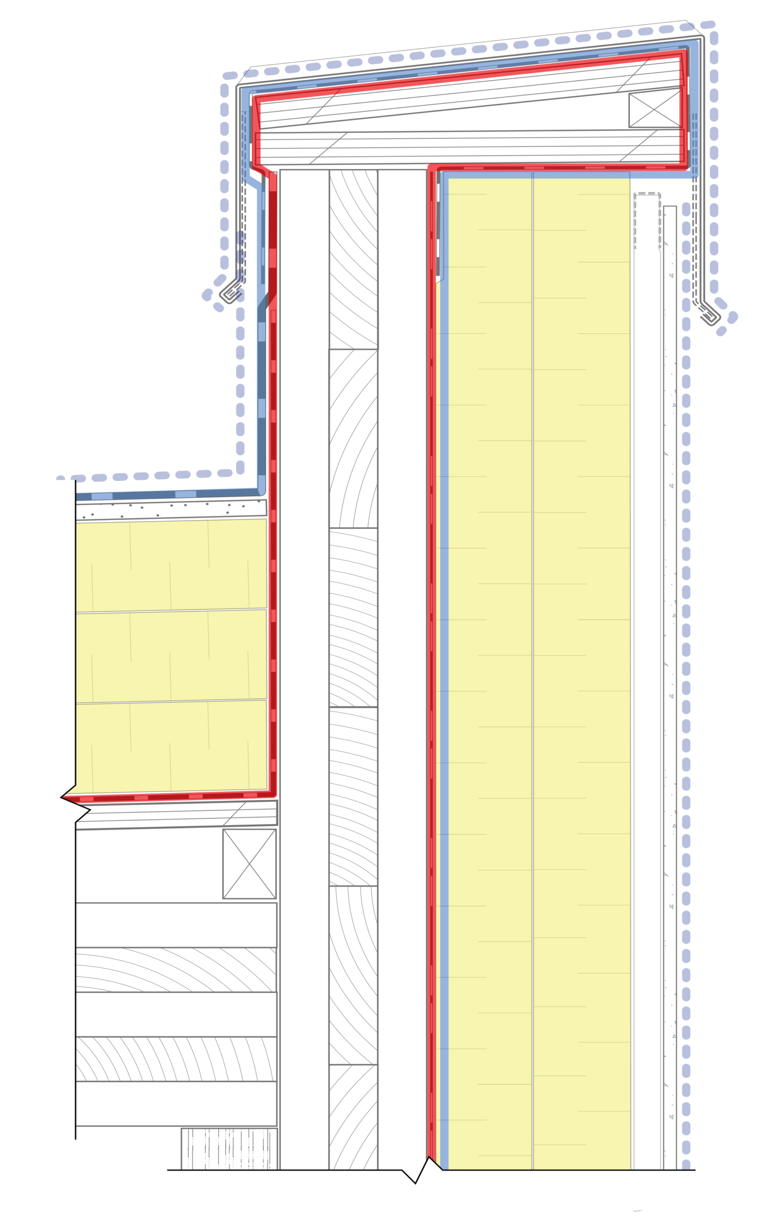
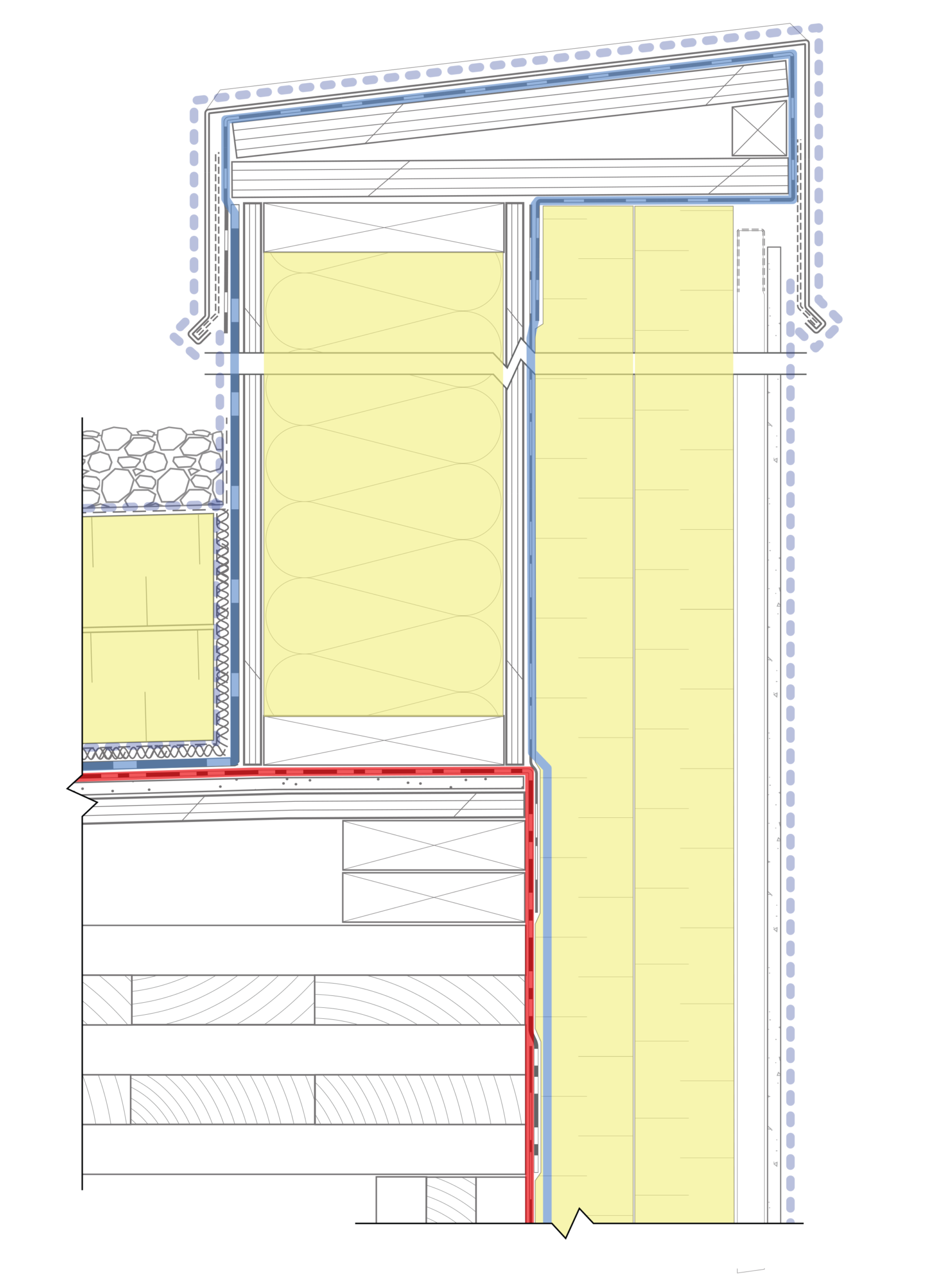
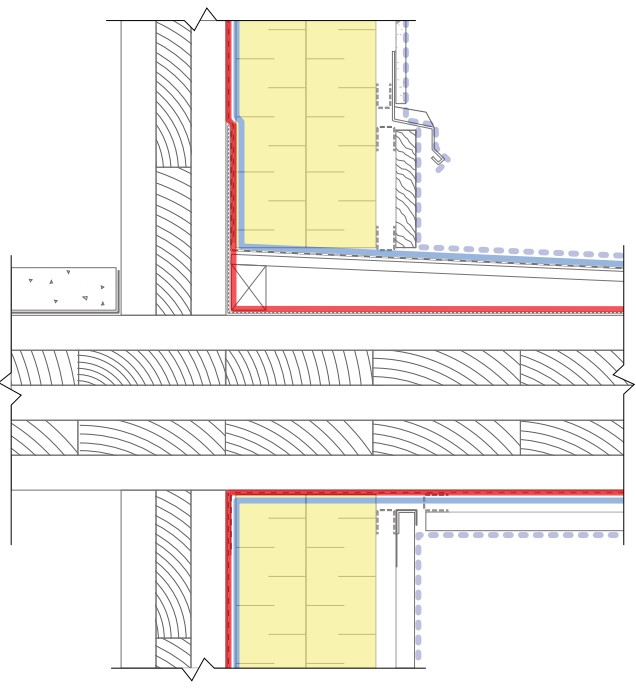
Parapets
In a balloon-framed parapet detail, the mass timber panel projecting through the roof insulation leads to a discontinuity in the thermal control layer (see image (a) at left). However, this detail still provides a lesser thermal bridge than that encountered on buildings with steel or concrete structures.
To further improve the thermal performance of the mass timber parapet, the design can incorporate insulation on all sides of the mass timber parapet. Alternatively, a platform-framed parapet can be filled with insulation (see image (b) at left).
Energy-Efficient Building Goals
Heat transfer isn’t the only consideration for reducing heat loss in the building. Air leakage, or the unintentional movement of air between the interior and exterior spaces, can significantly contribute to a building’s heat loss. Using an air barrier system on any building can reduce heat loss and improve indoor air quality.
In mass timber designs, it is common to use a fully-adhered exterior air barrier in roof and wall assemblies. Exterior air barriers typically have a lower rate of air leakage than interior air barriers. Furthermore, exterior insulation can improve the durability of an exterior air barrier by protecting it from damage and temperature fluctuations.
Tables 1 and 3 show examples of this air barrier placement in various wall and roof assemblies.
Premanufactured Panelized Systems
Mass timber includes prefabricated elements (e.g., beams, columns, and panels) that are craned into position on site. Designers and manufacturers are also incorporating components of the final building and enclosure into their prefabrication process, including thermal insulation and air barrier components.
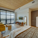
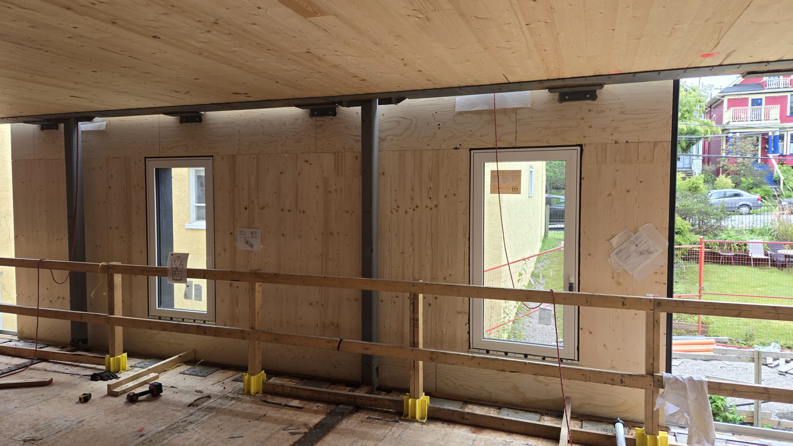
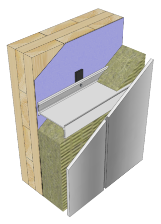
Prefabrication of enclosure systems enhances on-site construction efficiency and enclosure performance. It can also reduce construction phase moisture management risks. Prefabricated panelized assemblies can be installed with fewer steps and minimal exterior access. These assemblies may include air/water barriers, insulation, windows, doors, cladding, and trim (see Figure 2). For roof panels, prefabrication typically involves factory-installing the air and vapor control membrane.
Installing these elements on site can be labor intensive and time consuming. Therefore, using prefabricated panels with pre-applied enclosure elements is often more efficient and results in higher-quality installations due to controlled factory conditions.
The panel perimeters and connection points are the weakest points for air leakage and thermal control in prefabricated systems. To maintain airtightness, panelized systems often use flexible gasket materials. These gaskets provide airtightness from panel to panel without forming rigid connections. They accommodate panel movement due to building shifts, live loads, or seismic events. Furthermore, insulation fillers may be used between panel-to-panel connections, depending on the system, to provide thermal control layer continuity. On-site quality control, including visual inspection and performance testing, can increase confidence in airtight and thermally-continuous panel perimeters and connections.
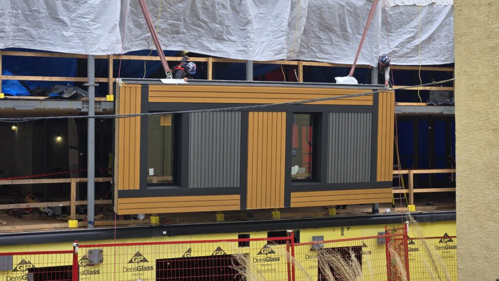
FIGURE 2: A CLT wall panel with a factory-installed air and water-resistive barrier membrane, insulation, cladding, and windows being hoisted into place
Related Resources
Consult these resources for more information on building enclosure design for mass timber buildings:
- RDH Building Science Inc. (2023). Mass Timber Building Enclosure Best Practice Design Guide V2.
- RDH Building Science Inc. (2025). Moisture Risk Management Strategies for Mass Timber Buildings V3.
- RDH Building Science. (n.d.). Control Layer Continuity for Mass Timber Building Enclosure Design. WoodWorks – Wood Products Council.
- RDH Building Science. (n.d.). Mass Timber Moisture Management for Construction. WoodWorks – Wood Products Council.
- WoodWorks – Wood Products Council. (n.d.). Exterior Walls in Mass Timber Buildings – Part 4: Panelization.
Article contributed by RDH Building Science Inc.