Expert Tips
Control Layer Continuity for Mass Timber Building Enclosure Design
Introductory level design guidance and effective practices for durable mass timber building enclosures
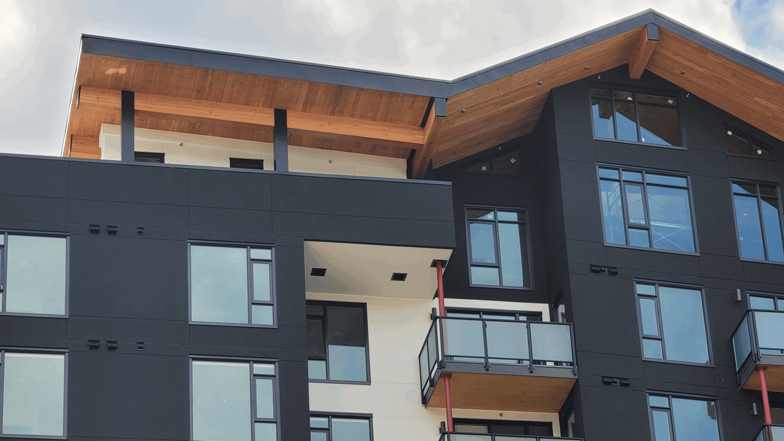
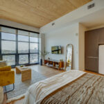
The building enclosure physically separates conditioned space from unconditioned space. Like all buildings, mass timber building enclosures are subject to environmental loads that must be managed.
This article focuses on managing water, air, thermal, and water vapor loads that act on the enclosure. Additional loads such as structural (e.g., wind, seismic, impact, etc.), fire, and sound are also important and are covered in other WoodWorks technical resources. See WoodWorks’ full resource library or get in touch for guidance on a specific topic.
The principles and practices outlined in this article highlight how designers and builders can effectively manage these environmental loads to create high-performance mass timber enclosures that support long-term performance, durability, and energy efficiency.
Introduction to Control Layers
The loads acting on the building enclosure vary based on the building’s interior and exterior conditions. These loads are managed by stand-alone materials or systems of materials called control layers. The four control layers covered in this article are described below.
- Water control layer: This layer manages the water load from rain, snow melt, ice melt, and groundwater. This layer includes water-resistant barriers (WRBs), flashings, trims, roof membranes, and drainage elements. A well-designed water control layer will maintain the dimensional stability of the wood, prevent corrosion of fasteners, and prevent fungal growth, decay, and aesthetic stains.
- Air control layer (i.e., the air barrier system): This layer manages the air load created by the air pressure difference between the interior and exterior of the building. This layer provides airtightness using membranes, sealants, and tapes. A well-designed air barrier also controls the transfer of sound, smoke, fire, and airborne contaminants, and improves the building’s energy performance.
- Thermal control layer: This layer controls the heat transfer that occurs when the temperature differs between the interior and exterior of the building. This layer includes thermal insulation and the minimization of thermal bridges to limit heat loss. A well-designed thermal control layer improves the building’s energy efficiency and occupant comfort.
- Vapor control layer: This layer controls the water vapor load. Water vapor in the air moves from high to low vapor pressure areas; vapor often moves from warm to cold areas because warm air can hold more moisture than cold air. This layer includes low-permeance materials to manage water vapor movement. A well-designed assembly provides vapor control to reduce condensation, dimensional wood changes, and fungal growth and/or wood deterioration, and importantly to allow for drying.
The relationships between building enclosure loads and control layers are summarized in Figure 1.
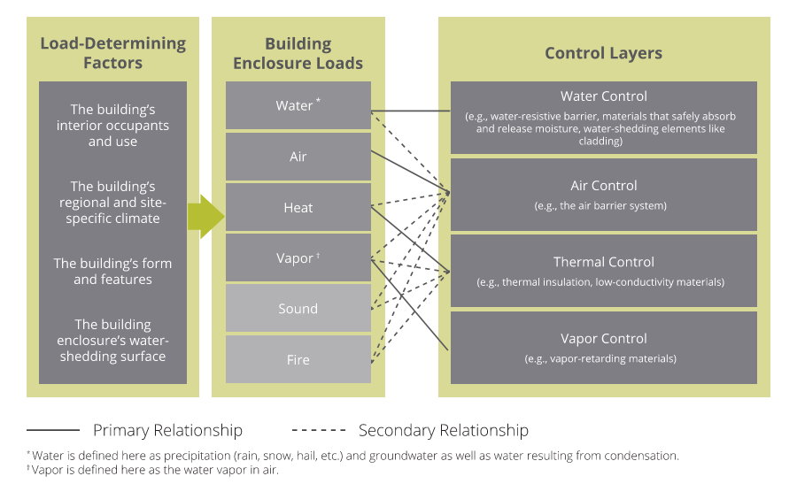
Figure 1: Building enclosure loads and their associated control layers. The load-determining factors inform the severity of the building enclosure loads. When a control layer is intentionally designed to control a specific load, that layer has a primary relationship with the building enclosure load. Some control layers also control other loads (i.e., secondary relationships).
Water Control Layer Principles
For mass timber enclosures, the most critical environmental load is often water.
Wood is a natural material that exhibits shrinkage and swelling due to moisture content changes. The rates of water absorption depend on the type of wood, grain, and exposure time. In simple terms, when wood absorbs water, it swells; and when wood dries, it shrinks. Dimensional changes are:
- Greatest in the direction of the annual growth rings (tangential).
- About half as much across the growth rings (radial).
- Very small along the grain (longitudinal).
Wood used in mass timber always has a mixture of growth ring orientations. Cross-laminated timber (CLT), where wood layers alternate at 90 degrees, is more dimensionally stable than light-frame wood due to the cross laminations restricting shrinkage and swelling. For glue-laminated timber (glulam), or nail-laminated timber (NLT) where layers of wood are oriented in the same direction, dimensional changes are greatest in the tangential direction.
Dimensional changes in wood can cause:
- Checking (if the wood rapidly swells and/or shrinks).
- Damage to cladding assemblies or other non-structural elements connected to a wood structure that are not designed to expand/contract with the wood.
- Gaps or collisions of different structural members or building assemblies.
If not properly managed, the mass timber’s exposure to moisture may also cause fastener corrosion and increase the risk of fungal growth and wood decay.
Water Control Practices for Mass Timber Walls
- Use a drained and ventilated cladding (i.e., rainscreen cladding) system in mass timber walls. This is a common practice in wetter regions of the US and Canada. The rainscreen strategy may seem excessive in some climates, but it provides necessary redundancy in water management design (Figure 2). Drainage is beneficial in modern wall designs to support redundant water control, and ventilation provides for drying of wetted surfaces, including the mass timber. Moreover, this ventilation of air bypasses the vapor permeance of the cladding, allowing any type of cladding to be used over a mass timber wall and allow outward drying.
- Avoid vapor-impermeable materials at the exterior of mass timber walls. These materials, including impermeable water/air/vapor control membranes and lower permeance exterior insulation types, have the potential to trap moisture within the mass timber panel and limit drying outwards through vapor diffusion.
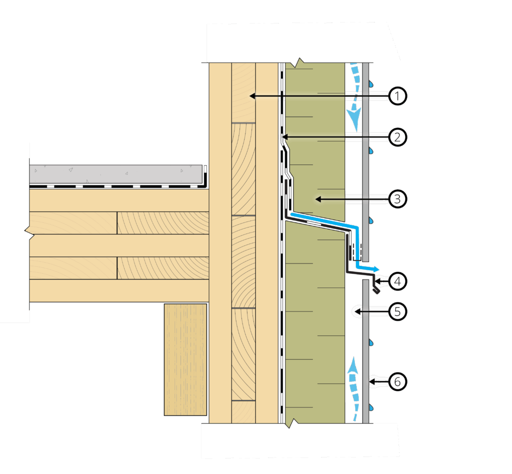
a) Wall section detail
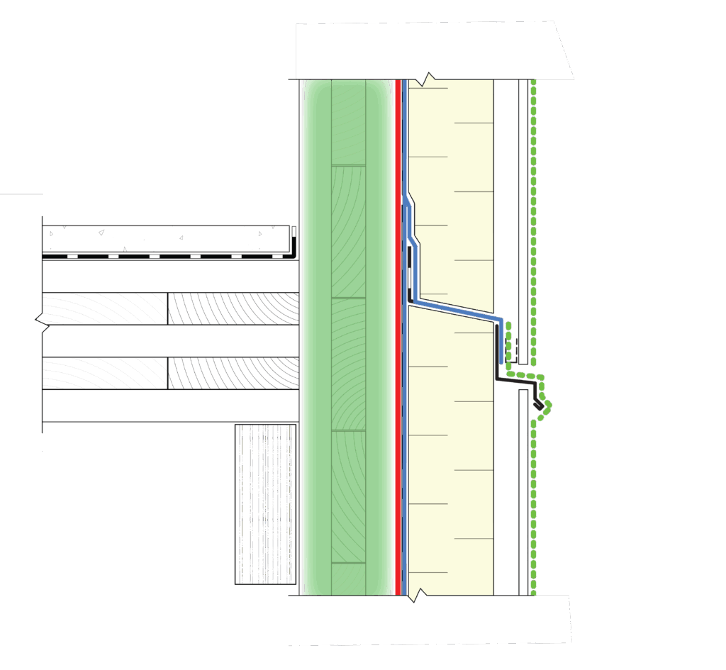
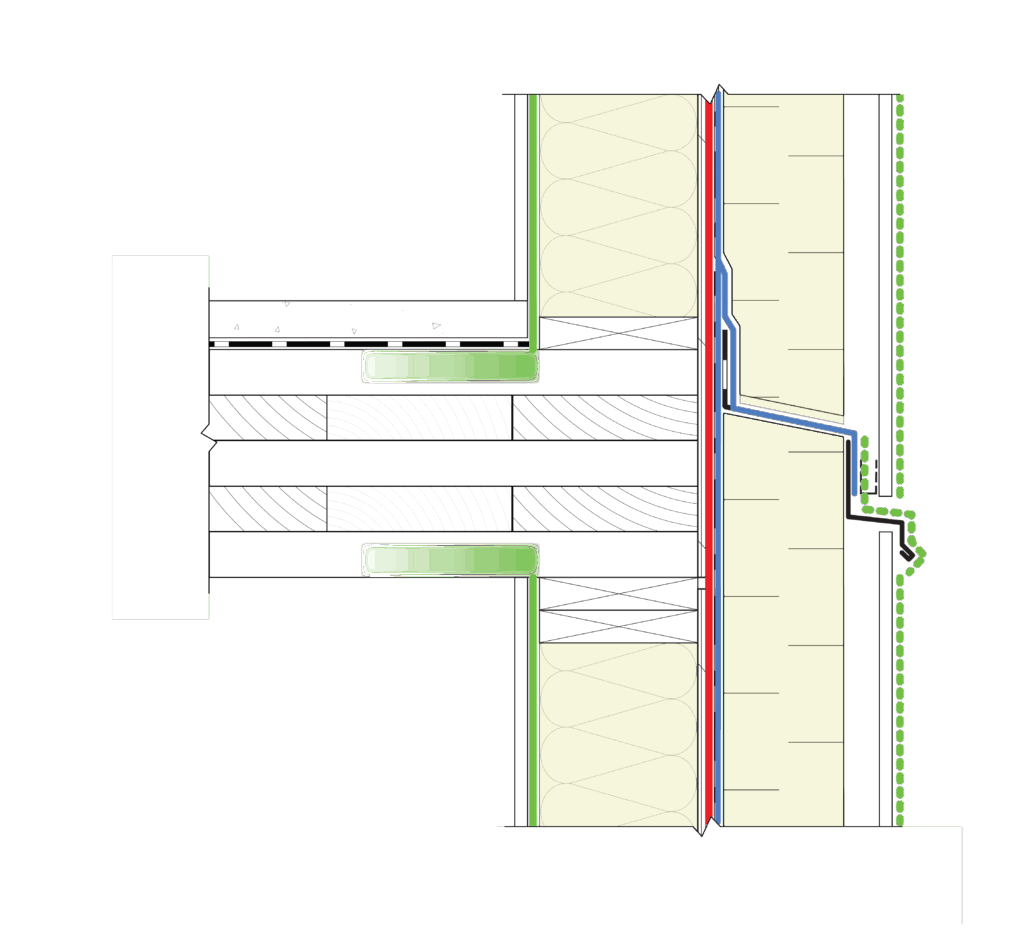
b) Control layer diagram
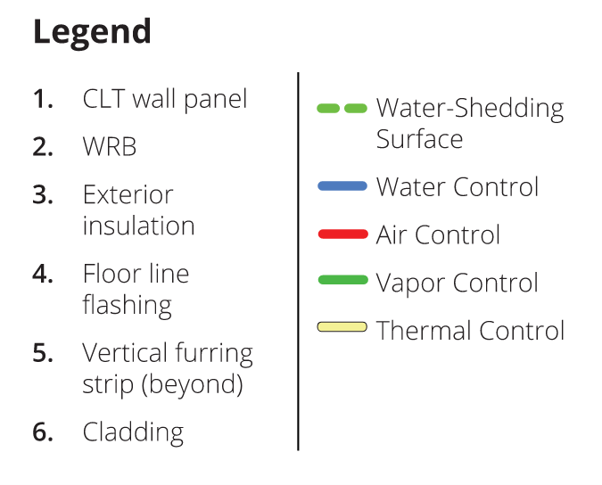
Figure 2: Typical rainscreen cladding. Water is first managed by the water-shedding surface, such as cladding (label #6) and flashings, and secondly by the WRB (label #2). In between these layers, the water load is reduced by the thickness and layering of the exterior insulation. Water that penetrates the water-shedding surface will run down the backside of the cladding, the strapping, the exterior insulation, or the WRB system before it reaches the flashing at floor levels and around wall penetrations. The WRB is the innermost and defined secondary plane of protection; it is often also sealed to perform as the air barrier system (see the air control section). Within this assembly, the CLT is vapor resistant and therefore controls vapor flow. It also supplements the exterior insulation here as CLT provides approximately R-1.2/inch. In this design, the mass timber backup wall is interchangeable with other backup wall types, such as a steel-stud or wood-stud framed wall. A framed backup wall would not change this design, except the placement or need for a vapor control layer would need to be reevaluated.
Commentary on Water Control Practices for Other Wall Types
Generally, the same water control principles that apply to mass timber rainscreen walls also apply to other backup wall types, such as steel-stud or wood stud-framed walls. Example section details and control layer diagrams for these walls are shown in Figure 3 and Figure 4.
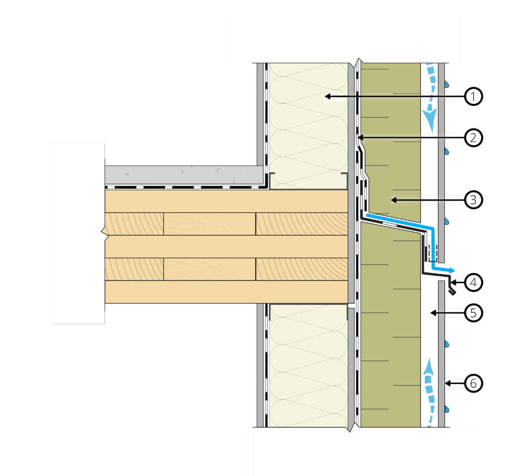
a) Wall section detail
b) Control layer diagram
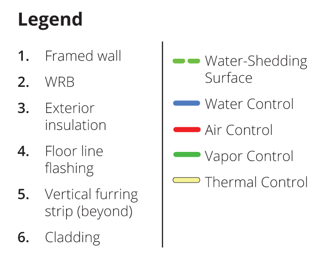
Figure 3: Wall section detail and control layer diagram for a steel stud-framed rainscreen wall.
a) Wall section detail
b) Control layer diagram
Figure 4: Wall section detail and control layer diagram for a wood stud-framed rainscreen wall.
Water Control Practices for Mass Timber Floors and Roofs
- Install a fully adhered multi-ply waterproof membrane on the roof. This practice supports the long-term performance of the roof assembly, especially when temporary roof membranes are not used. For low-slope conventional roofing, higher-performance, robust roofing membranes are recommended.
- Install a waterproof membrane at interior floor areas with high moisture exposure. During building occupancy, mass timber floor assemblies may not experience exterior water exposure (from rain/snow), but areas such as bathrooms, showers, and laundry rooms may be exposed to incidental water. Design these areas with a waterproof membrane and drains.
- Slope the roof deck to drain where possible. This approach provides simpler moisture management during construction and may allow for less robust waterproofing membranes during occupancy than flat roofs.
- Incorporate redundant design strategies. For example, an air/vapor barrier membrane can be placed directly on a sloped mass timber roof for additional backup drainage redundancy in the case of a leak.
- Monitor for leaks and damage. Leaks and topside damage at mass timber roofs can go undetected unless leaks are large enough to drip through the laminations or joinery of mass timber elements. The frequency and severity of water leaks can be reduced by installing a monitoring system (e.g., roof leak detection systems at the air/vapor barrier membrane or targeted sensors at high-risk locations) and performing regular condition assessments of the underside and topside of a roof assembly.
Using low-permeance materials on the exterior of mass timber roof and wall assemblies can potentially trap moisture within the mass timber elements and limit drying. Before covering or encapsulating mass timber with low-permeance materials, mass timber should be dried to a moisture content of 16% or less. Moisture readings need to be taken at multiple points, focusing on areas of deeper wetting like at panel joints with a calibrated moisture meter adjusted for the wood species.
Other Water Control Practices for Mass Timber Construction
- Incorporate flashing and drainage planes in mass timber roof and wall assemblies. This approach directs water away from the critical and exposed wood grain of mass timber in areas like parapets, window sills/heads, and other transitions or penetrations. In particular, the end grain of mass timber elements is more sensitive than the side grain and therefore will benefit from extra protection and deflection away from the areas where the end grain is exposed.
- Protect mass timber elements during construction. The general contractor and project team can prevent prolonged water exposure by developing a mass timber moisture management plan and implementing the plan during construction.
Air Control Layer Principles
The air control layer of a structure, also known as the air barrier system, controls airflow across the building enclosure. An effective air barrier system is important for reducing energy consumption associated with building space conditioning (heating and cooling), improving building resilience to wildfire smoke events, controlling other airborne contaminants, improving occupant thermal comfort, and minimizing water vapor movement and condensation.
In mass timber construction, interfaces between the panels and small spaces between panel laminations, especially when dried out in service, can allow air to move through the panels; thus, mass timber panels alone are not considered part of the air barrier system. Instead, careful selection and installation of an air barrier system is required to be integrated with the mass timber components.
An effective air barrier system has the following five characteristics:
- Continuity: The air barrier system is continuous at all joints, penetrations, and interfaces with other assemblies.
- Strength: The air barrier system is strong enough to transfer air pressures back to the supporting structure.
- Durability: The air barrier system is durable enough to perform throughout the expected service life of the building enclosure and demonstrates durability during the construction phase. It can withstand temperature fluctuations, building and wood substrate movement, air pressure differentials, and environmental exposures.
- Stiffness: The air barrier system is resistant to any pressure-induced loads from wind, stack effect, and/or mechanical system operations without significantly distorting, delaminating, or becoming damaged.
- Impermeable to air: The air barrier system resists airflow.
Air Control Practices for Mass Timber Construction
- Ensure air barrier continuity. Continuity is achieved by extending the air barrier system around all mass timber components, including up and over parapets, around soffits, and across floor lines.
- Use self-adhered membranes on mass timber panels. The membrane’s adhesion to the mass timber will integrally connect the two materials. This adhesion allows the membrane to resist both positive and negative airflow pressures and flanking air leakage at locations like parapets and other hard-to-seal interfaces. Mechanically attached membranes may be acceptable; however, in high wind exposure applications, a mechanically attached system may be insufficient to transfer air pressures to the structure without being damaged.
- Select durable materials. To be durable during the construction phase and throughout the structure’s lifetime, the air barrier materials must be able to withstand temperature fluctuations, movement of the building and wood substrates, and various environmental exposures.
- Seal penetrations, transitions, and membrane laps. Sealing these areas will help to achieve continuity of the air barrier system.
- Test for air leakage. Building codes may have certain airtightness testing requirements using blower door tests and/or minimum airtightness testing targets. Testing is often done by evaluating mock-ups, conducting whole-building airtightness testing, or testing representative suites.
Thermal Control Layer Principles
The greater the temperature difference between the indoor and outdoor environments, the greater the potential heat transfer across the building enclosure. Building codes in the US and Canada may have “prescriptive” requirements for minimum levels of insulation to reduce heat flow, but project-specific performance requirements may require more insulation. Tradeoffs are also common to adjust the amount of insulation levels within walls and roofs against other enclosure elements or mechanical systems to suit design constraints or as part of value engineering.
The mass timber itself also contributes to the thermal performance of the building enclosure. Mass timber has a relatively low thermal conductivity (i.e., good thermal performance) compared to other common structural materials like concrete and steel. The thermal resistance of wood per inch varies based on moisture content and species. For most North American softwood species, a thermal resistance of R-1.2 per inch can be assumed. Mass timber can also provide a thermal mass effect, which can help moderate temperature fluctuations and improve indoor comfort in certain building types and climates.
Thermal bridging is important to consider for all assemblies, whether they are made of mass timber or other structural materials. Thermal bridging occurs when a more highly conductive element, such as a metal cladding attachment, bridges a low-conductivity insulation layer and creates a path of lower resistance to heat flow. This bridge reduces the overall thermal performance of the insulation layer and the enclosure assembly, and may contribute to greater building energy use. Examples of thermal bridges within the field of the wall include fasteners for the cladding and roof assembly layers, and mass timber protrusions such as parapets, beams, and balconies.
Thermal Control Practices for Mass Timber Construction
- Place insulation outboard of the mass timber panel. This location keeps the wood panel closer to the indoor temperature to reduce condensation risk and to limit temperature and humidity fluctuations (Figure 5). This placement is suitable for all climates.
- Use semi-rigid or rigid insulation with a sufficient R-value. Select the insulation R-value based on the climatic conditions for the roof, wall, and floor assemblies. Most building codes across the US and Canada prescribe minimum levels of insulation. The vapor permeance of the insulation is also a consideration during selection of insulation (refer to the following section on vapor control principles and Figure 6 for more detail).
- Achieve continuous insulation. Provide continuous insulation across all mass timber assembly surfaces. Limit the length of linear thermal bridges, such as uninsulated parapets, and point thermal bridges, such as penetrating beams and steel brackets.
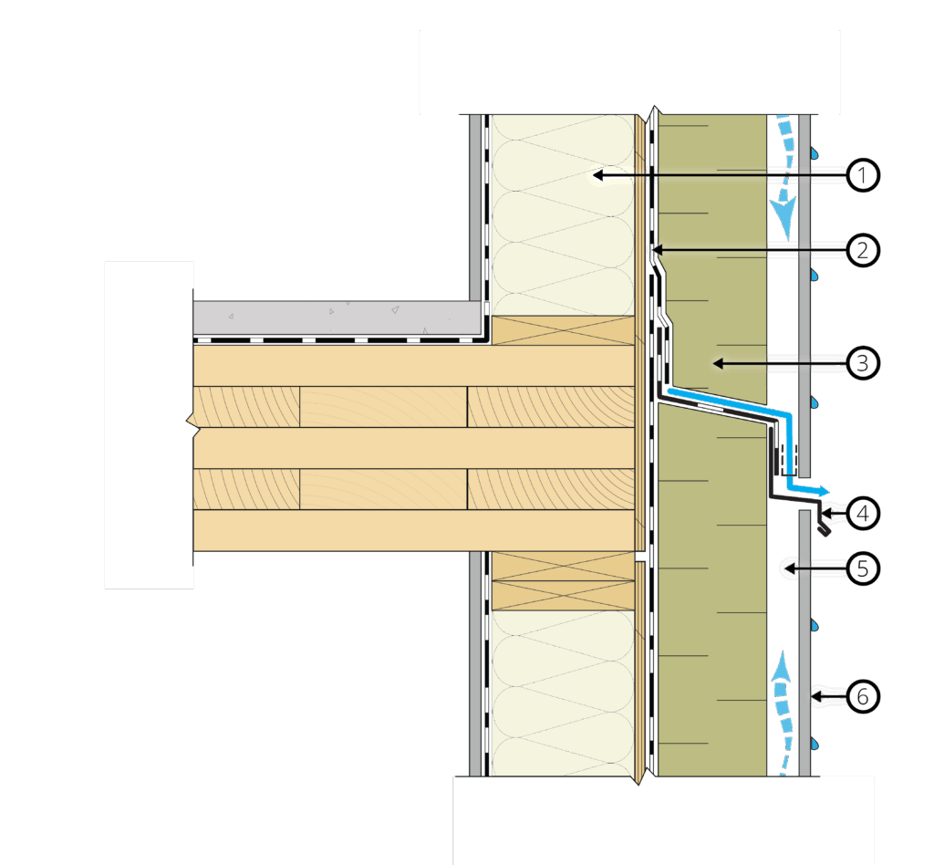
- Design attachment points with low-conductivity materials. Materials such as stainless steel, fiberglass, wood blocking, and/or intermittent attachments will reduce the impacts of thermal bridging through insulation in lieu of continuous metal furring (Figure 5).
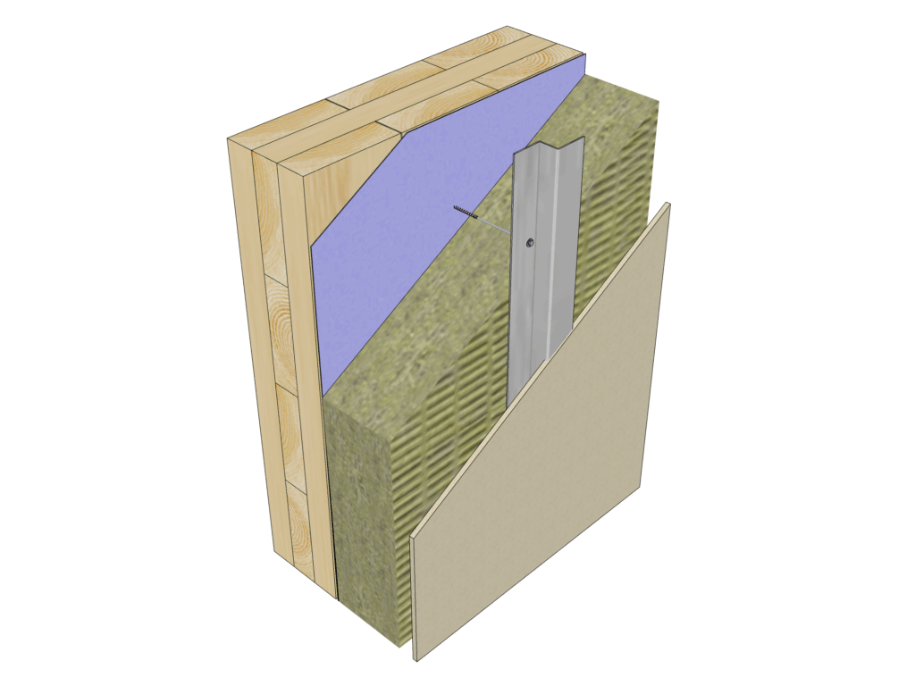
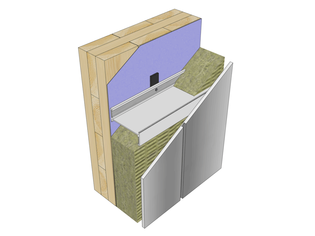
Figure 5: Examples of various cladding attachment systems. a) Clip and rail system – the cladding is attached to vertical or horizontal girts. The girts (or rails) are attached to the intermittent clips that bridge the exterior insulation and are attached to the mass timber structure. b) Long screw with furring strips – this is a cost-effective and thermally efficient option for the attachment of light- to medium-weight claddings. Cladding is attached to steel furring strips or treated vertical wood strips placed against the faces of the exterior insulation. c) Horizontal girts – girts are shimmed to provide a continuous drainage plane at the face of the WRB (shims also seal around girt fastener penetrations through the membrane) and at the backside of the cladding. Horizontal girts bridge the insulation, which can significantly reduce the performance of the exterior insulation unless non-metal girts are used.
Vapor Control Layer Principles
Wood gains or loses moisture depending on the relative humidity (RH) and temperature of the surrounding air. With care in the manufacturing, transport, storage, and construction of mass timber, the moisture content of the wood will change within only a small range. Consequently, wood shrinkage or swelling will be much smaller. When the wood no longer gains or loses moisture, it has reached equilibrium with the environment and RH.
Water vapor transport across a mass timber assembly can be managed by relying on the mass timber’s ability to function as a vapor retarder and by controlling air leakage across the enclosure.
Airflow transports significantly larger amounts of water vapor than vapor diffusion alone; however, both transport mechanisms must be controlled properly in relation to the building’s interior and exterior climatic conditions.
Adding a vapor barrier or other low-permeability materials on the interior of a mass timber wall or roof is not recommended because it reduces the drying potential of the mass timber. This strategy is straightforward in wall assemblies but becomes more challenging to achieve in roof assemblies, where vapor-impermeable water control layers are often necessary.
Vapor Control Practices for Mass Timber Construction
- Consider interior and exterior climate conditions when locating insulation and vapor control layers. Ensure that the potential for assembly drying is maintained and that the risk of condensation forming within the assembly is minimized.
- Rely on mass timber’s ability to function as a vapor retarder and install vapor-permeable membranes in mass timber walls. Avoid using a vapor barrier or other low-permeability material that reduces the drying potential on either side of the mass timber panel (Figure 6).
- Install an air barrier system. Using an air barrier in both roof and wall assemblies reduces the flow of moisture-laden air across the mass timber enclosure. The continuity of an exterior air barrier system is generally easier to achieve than that of an interior air barrier system for wall assemblies.
- Avoid encapsulating mass timber assemblies with impermeable materials. For example, a mass timber floor with a cementitious topping and membrane above, and an impermeable membrane below, would be a poor design.
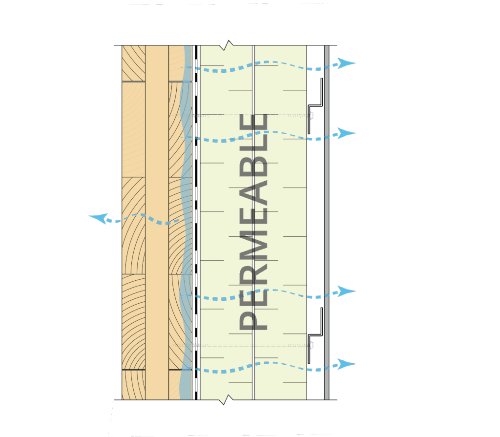
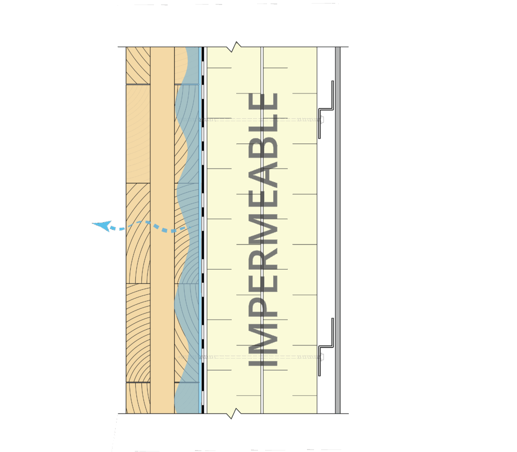
Figure 6: Example wall assembly (plan view) in a heating-dominant climate. This example shows the relative direction of drying (see blue arrows) toward the building exterior. a) Vapor-permeable exterior insulation, vapor-permeable air barrier, and WRB membrane are used. b) Vapor-impermeable exterior insulation or impermeable air barrier and WRB membrane are used; while the interior laminations of the CLT can dry out relatively quickly, the outer lamination behind the impermeable membrane and the insulation can take months or years to dry out fully. Note that the need for vapor-permeable layers to support assembly drying also applies to floor/soffit assemblies.
Importance of Control Layer Continuity
Continuity of the control layers is a key strategy in the design and construction of building assemblies. This continuity applies to all buildings, not just those constructed with mass timber. Small discontinuities can lead to unwanted water intrusion, air leakage, or thermal losses.
For example, discontinuity in the water control layer can lead to water ingress into the assembly and/or the building. Small holes created by fasteners (even those that look to be sealed through “self-sealing” impermeable waterproofing membranes) have been found to allow for water ingress, resulting in failure of mass timber components and assemblies because of their inability to dry out. To reduce this water ingress risk, keep water away from fasteners, particularly those connecting directly into mass timber elements, and provide adequate sealing at these locations.
Water that becomes trapped behind membranes or other layers without a clear path for drainage and limited ability to dry out can lead to durability and performance issues. Common problems include wood decay due to moisture exposure and reduced thermal performance of the assembly if the insulation becomes saturated. Figure 7 shows three examples of control layer continuity for different mass timber interface conditions. These details generally rely on the mass timber for vapor control and use vapor-open materials to reduce condensation risk and encourage drying.
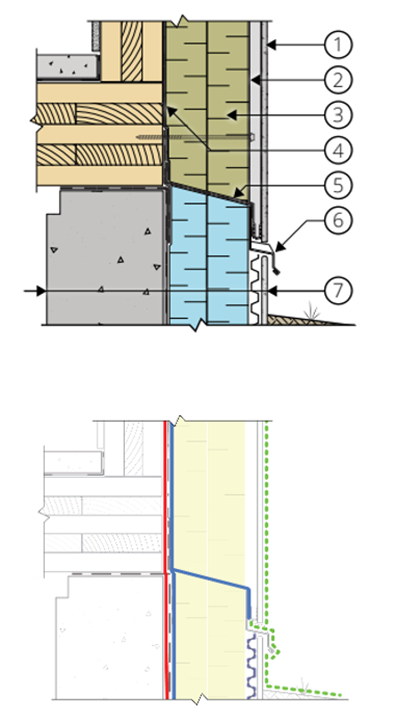
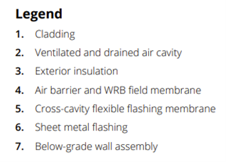
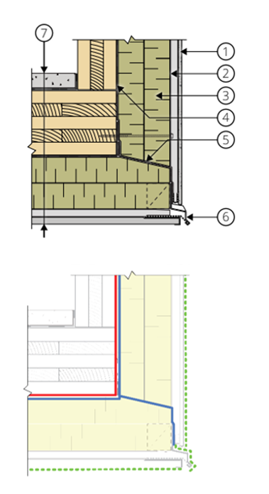
Figure 7: Typical mass timber details at a) an at-grade condition, b) a balcony-to-wall condition, and c) a soffit-to-wall condition. The water-shedding surface, water control, air control, and thermal control layers are depicted. The vapor control is provided by the mass timber panel in heating-dominated climates and is not shown in this figure for clarity. The air and water control layers may sometimes, but not always, be satisfied by a single product.
General Practices for Continuity of Control Layers in Mass Timber Construction
- Use the concept of control layers to evaluate assemblies and details. This approach allows the designer, contractor, and owner teams to understand the role and importance of each enclosure material or system. The project team can then identify and evaluate layers that are missing, discontinuous (if required to be continuous), or inappropriately redundant. This approach can also limit the gaps in the construction documents and reduce excessive materials and related costs.
- Confirm control layer continuity at penetrations, joints, connections, and details within the building enclosure. Control layers are often first assigned to building assemblies. The continuity of these layers needs to extend to the building enclosure details to achieve the expected performance. Examples include window or door rough openings, electrical penetrations, parapets, soffits, and the base of the wall.
- Implement quality control practices. Contractors can support control layer continuity by implementing strict quality control practices during the installation of the building enclosure. Strict quality control practices will pay particular attention to system and material transitions, such as at horizontal to vertical interfaces, roof transitions, etc. These practices could also include an enclosure quality assurance review throughout construction by a third party and commissioning of the air barrier.
Related Resources
Consult these resources for more information on building enclosure design and moisture management for mass timber buildings:
- RDH Building Science Inc. (2023). Mass Timber Building Enclosure Best Practice Design Guide – Version 2.
- RDH Building Science Inc. (2025). Moisture Risk Management Strategies for Mass Timber Buildings Version 3.
- WoodWorks. (2020). The Modular Enclosure: Protect Your Investment During Every Phase.
- WoodWorks. (2025). Mass Timber Moisture Management During Construction.
- Think Wood. (2024). Nail-Laminated Timber Canadian Design and Construction Guide 2.0
- FP Innovations. (2019). CLT Handbook
Article contributed by Laura Simandl, Bailey Brown, Graham Finch, Margaret Thayer, and others from RDH Building Science, May 2025.
RDH Building Science is a leading consulting and engineering firm specializing in climate-responsive, low-carbon, and energy-efficient solutions across North America. We have long been at the forefront of North America’s most innovative mass timber structures, offering enclosure consulting/engineering and commissioning, research and development, moisture management consulting, and specialized resource and guidance.