Expert Tips
Calculating the Capacity of Multiple Shear Walls in a Line
Overview of the two methods of shear wall distribution in SDPWS for light-frame wood buildings

This article references the American Wood Council’s (AWC) 2021 Special Design Provisions for Wind and Seismic (SDPWS), AWC’s 2018 National Design Specification (NDS) for Wood Construction, and AWC’s 2018 NDS Supplement.
When a building design has multiple light-frame wood walls sheathed with wood structural panels along the same line of lateral resistance, it is important to determine the appropriate capacity of each wall to verify that the specified construction is adequate. Where shear wall segments are the same length and construction (i.e., sheathing type and thickness, nailing, blocking, etc.), it is assumed that each wall has the same capacity. When they are unequal lengths, determining the shear capacity of each segment is more involved.
SDPWS provides two options for determining shear distribution to these shear walls. One method, referred to as the equal deflection calculation approach, is given in Section 4.3.5.5.1 and demonstrated in commentary Example C4.3.5.5.1-1. The other method comes from the exceptions to the same SDPWS section, demonstrated in commentary Example C4.3.5.5.1-2; it is referred to here as the simplified shear distribution approach.
For either approach, the shear walls should have the same combination of sheathing, blocking, and fastener types and layout as noted in the commentary. Both methods have the basic assumption that the distribution of forces to each wall will be based on their relative stiffness. For the equal deflection calculation approach, it is assumed that the walls will deflect equally since they are connected by a continuous member (e.g., double top plate, continuous rim joist, etc.). Alternatively, in the simplified shear distribution approach, the capacity of each shear wall is based only on its relative length.
Design Example
To illustrate both options, calculations will be performed for an example wall with multiple shear wall segments subjected to a wind load of 6,325 pounds. In both methodologies, the total design capacity of the shear wall line (i.e., the sum of the resisting forces in each shear wall) will be determined and compared to the design load to verify that the wall construction is adequate. The wall is 10 ft tall and consists of shear wall 1 (SW1), which is 4 ft wide, and shear wall 2 (SW2), which is 9 ft wide (Figure 1).
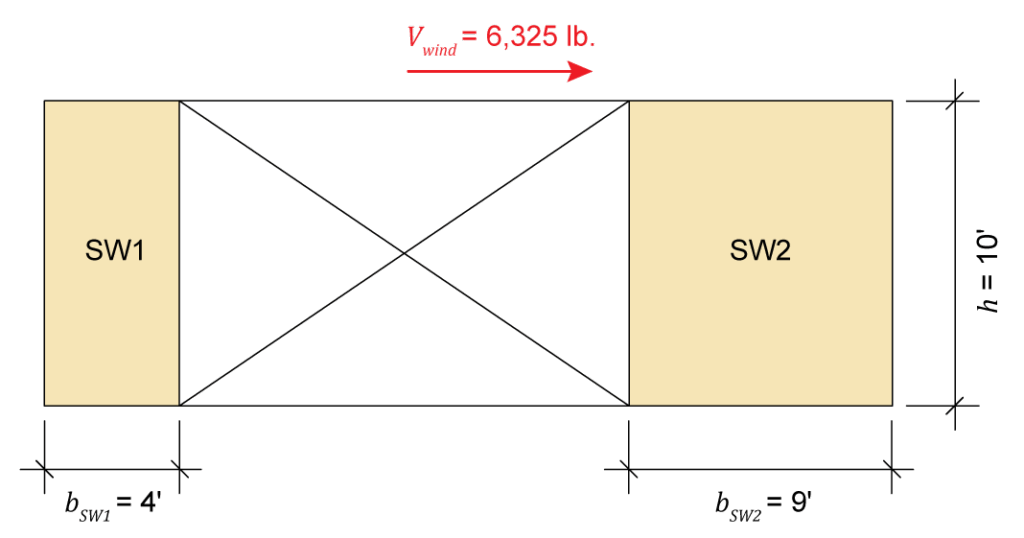
Figure 1: Example shear wall elevation
Both wall segments have the same construction, consisting of 2×6 spruce-pine-fir (SPF) spaced at 16 in. o.c. with two 2×6 posts at each end and hold-down anchors at the inside face of each end post. The walls are sheathed with 15/32-in. wood structural panel (WSP) sheathing, which is fastened with 8d nails at 3 in. o.c. at the panel edges (Figure 2).
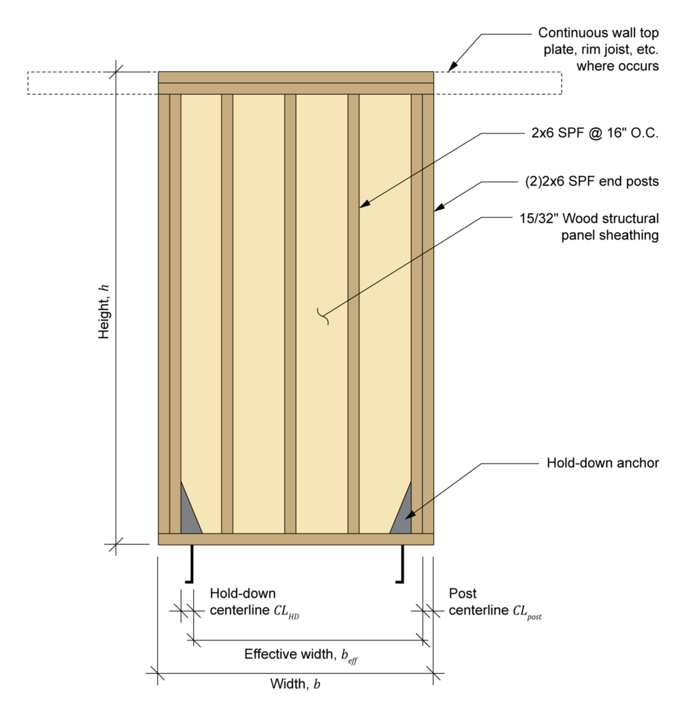
Figure 2: Shear wall construction
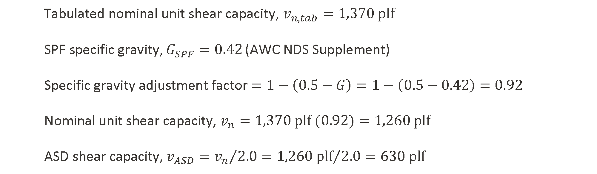
The allowable stress design (ASD) capacity for the wall construction is determined using SDPWS Table 4.3A. For the specific sheathing and nailing pattern, the tabulated nominal unit shear capacity is 1,370 plf. However, per footnote 3, since the wall framing is SPF (as opposed to Douglas-fir-larch or southern pine), the tabulated capacity must be reduced by the specific gravity adjustment factor, equivalent to 1-(0.5-G), where G is the specific gravity of the framing lumber. The ASD capacity, per footnote 1, is then determined by adjusting the nominal capacity in accordance with SDPWS Section 4.1.4; for ASD, the allowable shear capacity is divided by a factor of 2.0 for wind loading and 2.8 for seismic loading (different factors apply for load-resistance factor design, or LRFD).
Method 1: Equal Deflection Calculation Approach
Check Wall Segment Aspect Ratios
One of the first steps in assessing any shear wall is to verify that the wall segment qualifies for use as a shear wall. SDPWS specifies the maximum shear wall aspect ratios (height divided by width) for various types of sheathed walls in Table 4.3.3 (Figure 3). Note that, although the table indicates a maximum aspect ratio of 3.5:1 for blocked wood structural panels, SDPWS Section 4.3.3.2 specifies that, for segments with an aspect ratio between 2:1 and 3.5:1, the nominal shear capacity must be reduced by the aspect ratio factor, equivalent to 1.25 – 0.125h/b for WSP.
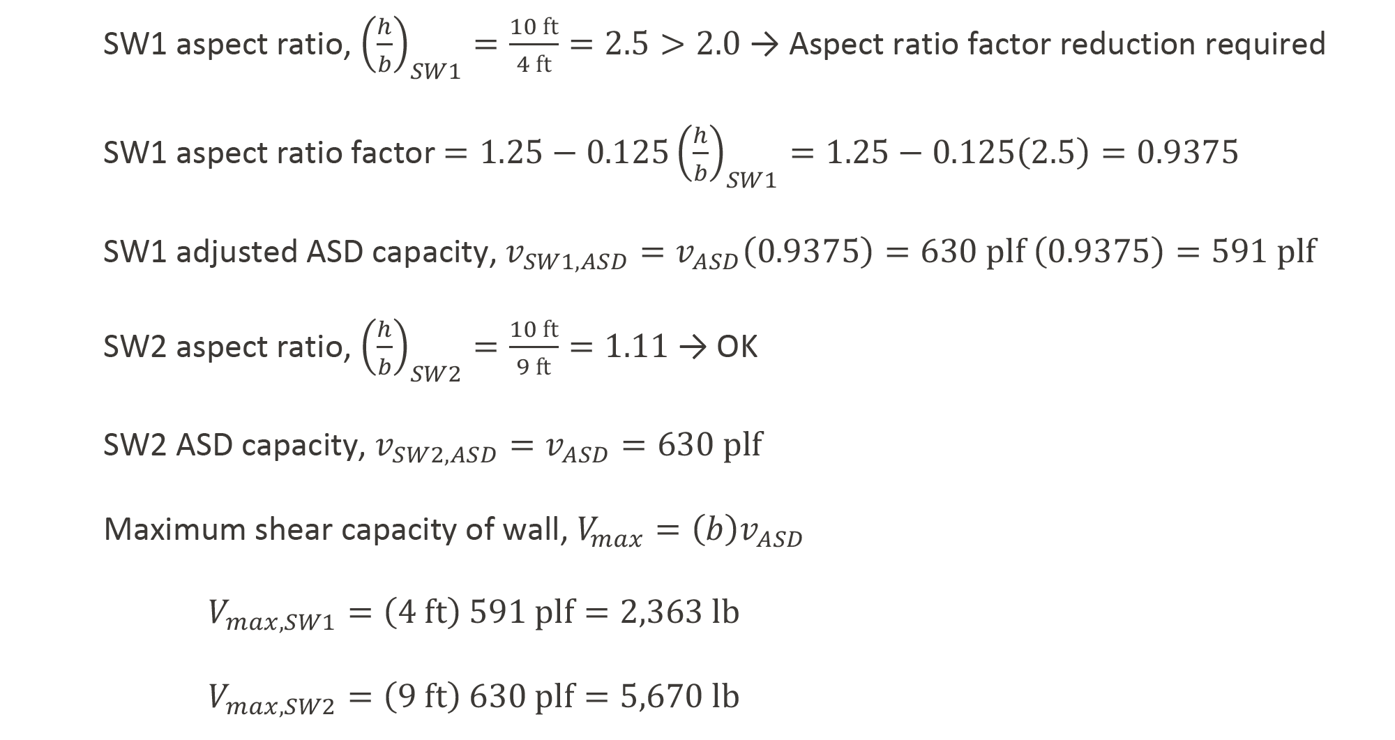
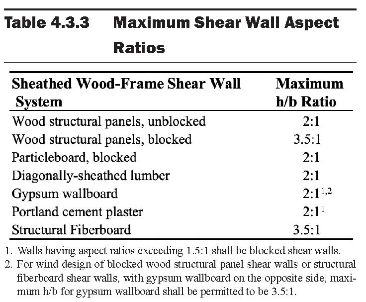
Figure 3: Maximum allowable shear wall aspect ratios per SDPWS Table 4.3.3
Calculate Deflection of Wall Segments
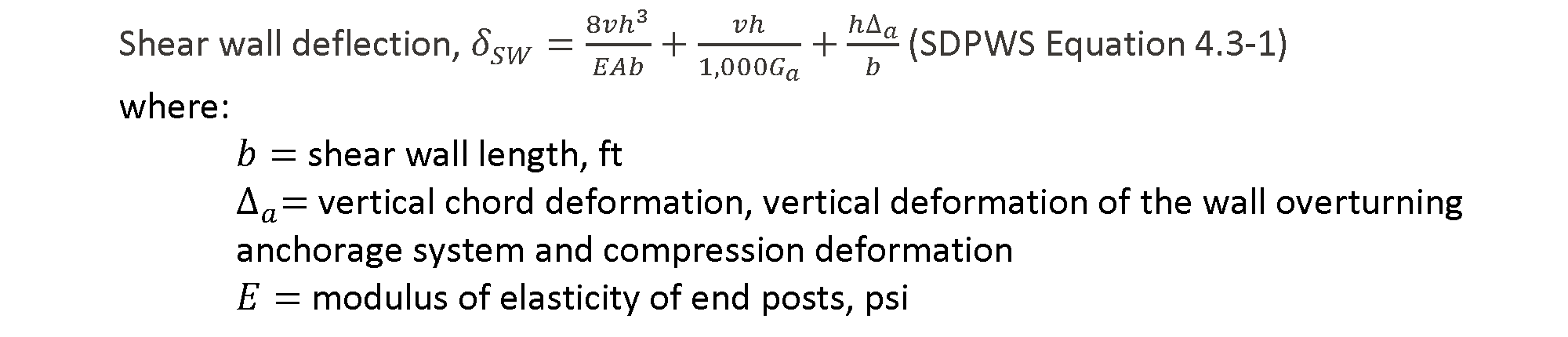
The deflection of each wall at its capacity is used to determine the relative stiffness of the walls. Note that, while the deflection calculations performed here are used to determine relative wall stiffness, they are based on ASD-level loads and neglect the impacts of gravity loading, meaning they are not appropriate for checking drift limits per ASCE 7. Shear wall deflection is calculated using the three-term equation found in SDPWS Section 4.3.4.1, with the three terms representing deflection due to bending of the end posts, shear due to panel shear deformation and nail slip, and bending and deformation of the wall anchorage, respectively. In Commentary Section C4.3.4, a four-term equation is also provided where deformations due to panel shear and nail slip are determined separately. The four-term equation includes a non-linear relationship between the force and nail slip that produces lower deflections than the three-term version at force levels lower than the capacity of the wall. The three-term equation is a simplified and more commonly used form of the four-term equation. Either can be used; however, the same equation should be used for all shear walls in a line.

Calculate Shear Wall Vertical Chord Deformation, Δa
While most of the terms in the deflection equation can be determined fairly simply based on wall configuration and values found in SDPWS and the NDS Supplement, the vertical chord deformation term, Δa, is more involved. This value accounts for vertical deformations at both ends of the shear wall segment, including deformations of the anchorage system at the uplift end of the wall (ΔT) and deformations due to crushing of the wall bottom plate at the compression end of the wall (ΔC). Additionally, per clarifications provided in the 2021 edition of SDPWS, the wall rotation caused by the actual location of the anchorage placement with respect to the end of the shear wall is a factor in determining Δa. The equation for shear wall vertical chord deformation is given in SDPWS Commentary Example 4.3.4-2. This example also includes a graphical depiction of the vertical deformation sources, which is included here as Figure 4.

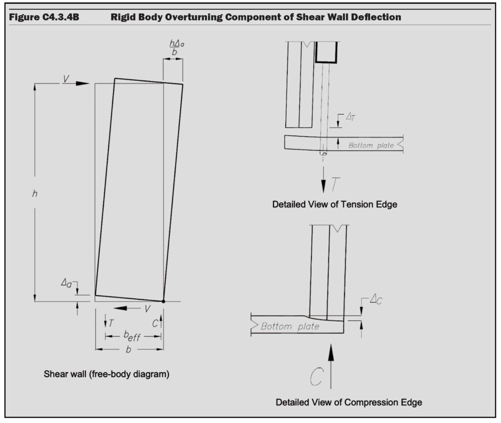
Figure 4: Shear wall vertical deformation term (SDPWS Figure C4.3.4B)
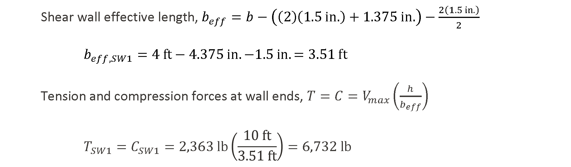
To calculate vertical chord deformation at the wall’s maximum allowable shear load, vASD, the tension (T) and compression (C) forces at the wall ends must be determined. For these walls, the hold-down rod will be 1.375 in. from the inside face of the end post and the compression force is assumed to occur at the center of the end post. Calculations for SW1 are shown, and the same calculations will be required for all wall segments.
Calculate Vertical Chord Deformation due to Tension, ΔT
The capacity and maximum elongation of the selected tension anchorage is often found in the manufacturer’s literature. The elongation of the anchorage at the tension load can then be determined by assuming deformation of the anchorage is linear. From the hold-down manufacturer, the vertical elongation of the wall anchorage (∆HD) used in this example is 0.137 in. at its maximum capacity (THD), 8,030 lb.

Calculate Vertical Chord Deformation due to Compression, ΔC
The deformation at the compression end of the wall is due to crushing where the wall end post bears on the wall bottom plate. As outlined in NDS Section 4.2.6, reference compression perpendicular to grain, Fc⊥, occurs at a deflection of 0.04 in. The same section of the NDS states that, per Equation 4.2-1, at 0.73 Fc⊥, deflection is 0.02 in.; we will call this Fc⊥,0.02. Where the actual crushing pressure is between Fc⊥,0.02 and Fc⊥, the deformation due to compression at the wall’s maximum shear load can be calculated assuming linear deformation. This relationship is graphically presented in SDPWS Figure C4.3.4A.
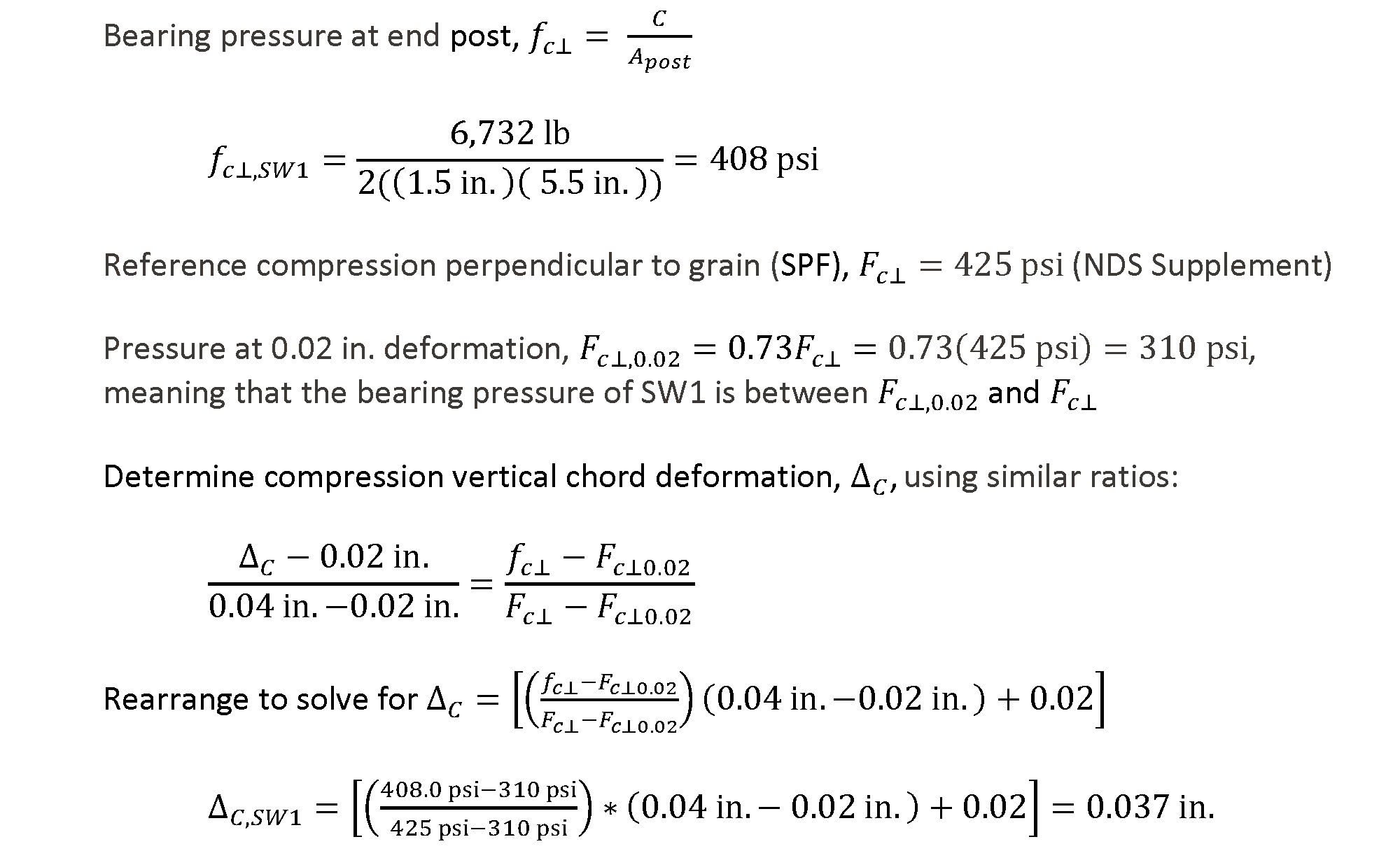
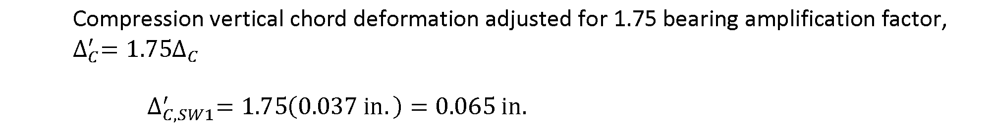
NDS Commentary Section C4.2.6 notes that the reference design compression values are based on tests conducted with 2-in.-wide steel plates bearing on wood. Where two wood members were both loaded perpendicular to grain, the deformations were found to be approximately 2.5 times that of a metal bearing plate condition (i.e., a 150% increase). It therefore follows that, when only one wood member is loaded perpendicular to grain, the deformation will increase by a factor of approximately 1.75 from that of a metal bearing plate (i.e., a 75% increase). Although this amplification factor is not required in the NDS or included in the SDPWS shear wall examples, the Engineer of Record should determine if this factor needs to be applied.1 For thoroughness in this example, the amplification factor will be applied to the crushing values.
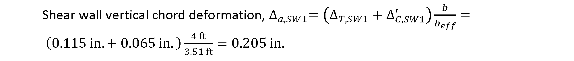
With deflections at each end of the wall determined, total vertical chord deformation of the wall overturning anchorage system, adjusted for the location of the compression and tension deformations, can be calculated.
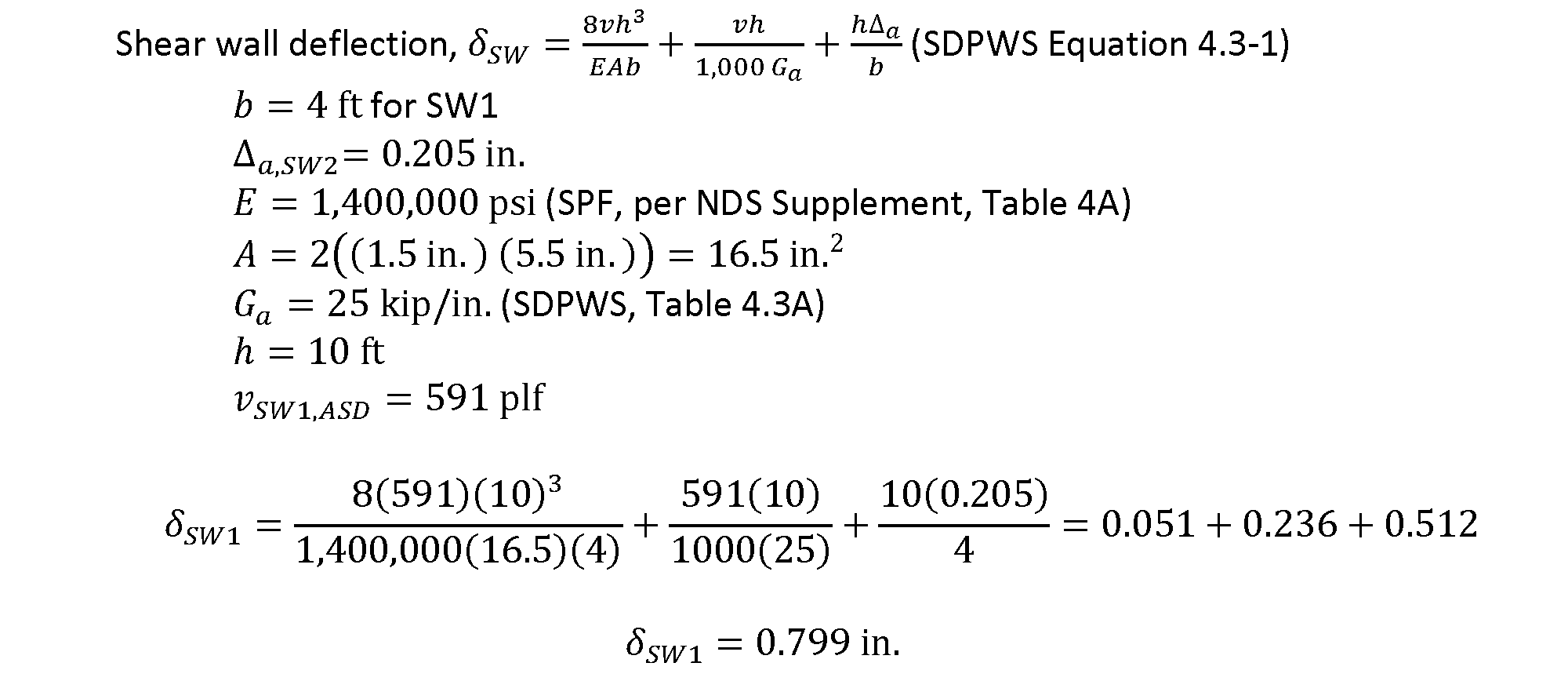
With the shear wall vertical chord deformation determined, SW1 deflection at the wall’s maximum shear load, using the equation provided above, can be calculated.
Performing similar calculations for SW2 at its ASD capacity, 630 plf, results in a deflection, 𝛿SW2, of 0.485 in.
Determine Shear Capacity of Walls in the Line
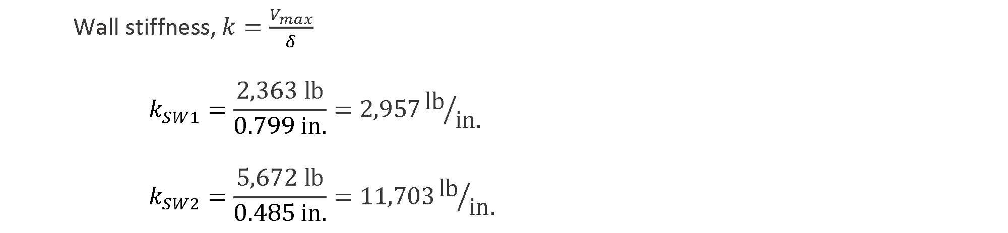
Based on the calculated deflections at each wall capacity, the stiffness, k, of each wall can be determined.
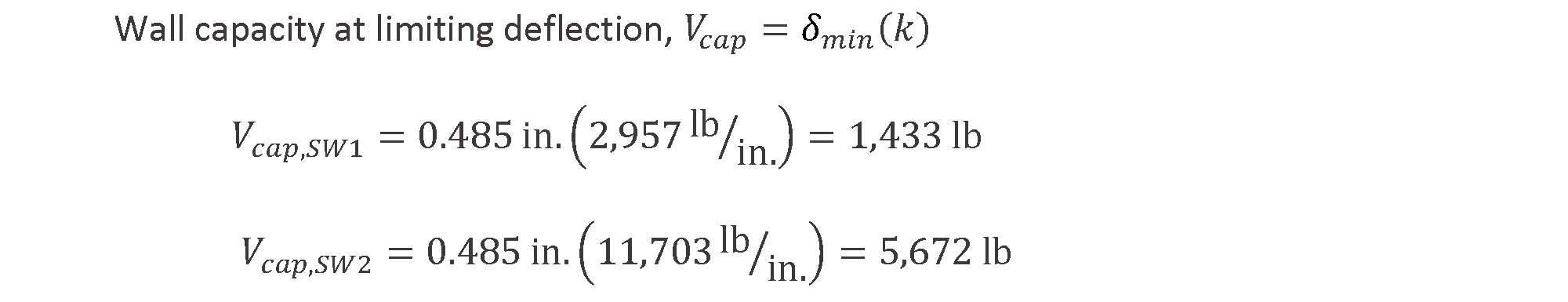
When using the equal deflection method, the wall with the smallest deflection at its capacity will limit the combined capacity of all of the walls in that line. In this example, SW2 has the minimum deflection, 𝛿min, at its capacity (0.485 in. < 0.799 in.), and the wall line capacity is determined at that deflection.
Compare Total Shear Wall Capacity to Shear Loading
The final step in the equal deflection calculation approach is to verify that the capacity of the shear walls along the line of resistance is greater than the loading on the wall and, therefore, that the specified walls are acceptable (Figure 5).

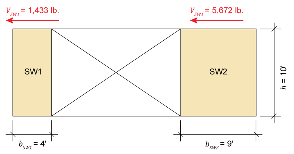
Figure 5: Shear wall capacities using the equivalent deflection approach
Compare Shear Wall Capacity to Shear Loading
For completeness, the shear load on each wall at the controlling deflection is compared to the maximum shear capacity of the wall.
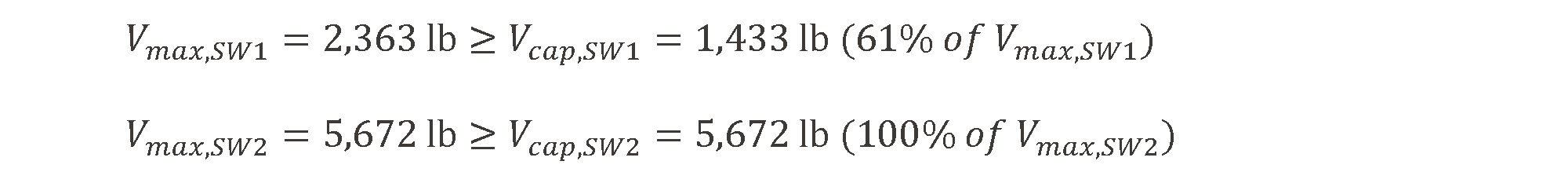
In the calculated distribution of forces, each wall has a shear force at the controlling deflection (Vcap) that is not greater than its maximum capacity (Vmax), and one wall (SW2) has an applied shear force equal to its capacity. If the steps above are performed correctly, this should always be the result and is a valuable method for checking the calculations.
Method 2: Simplified Shear Distribution Approach
Check Wall Segment Aspect Ratios
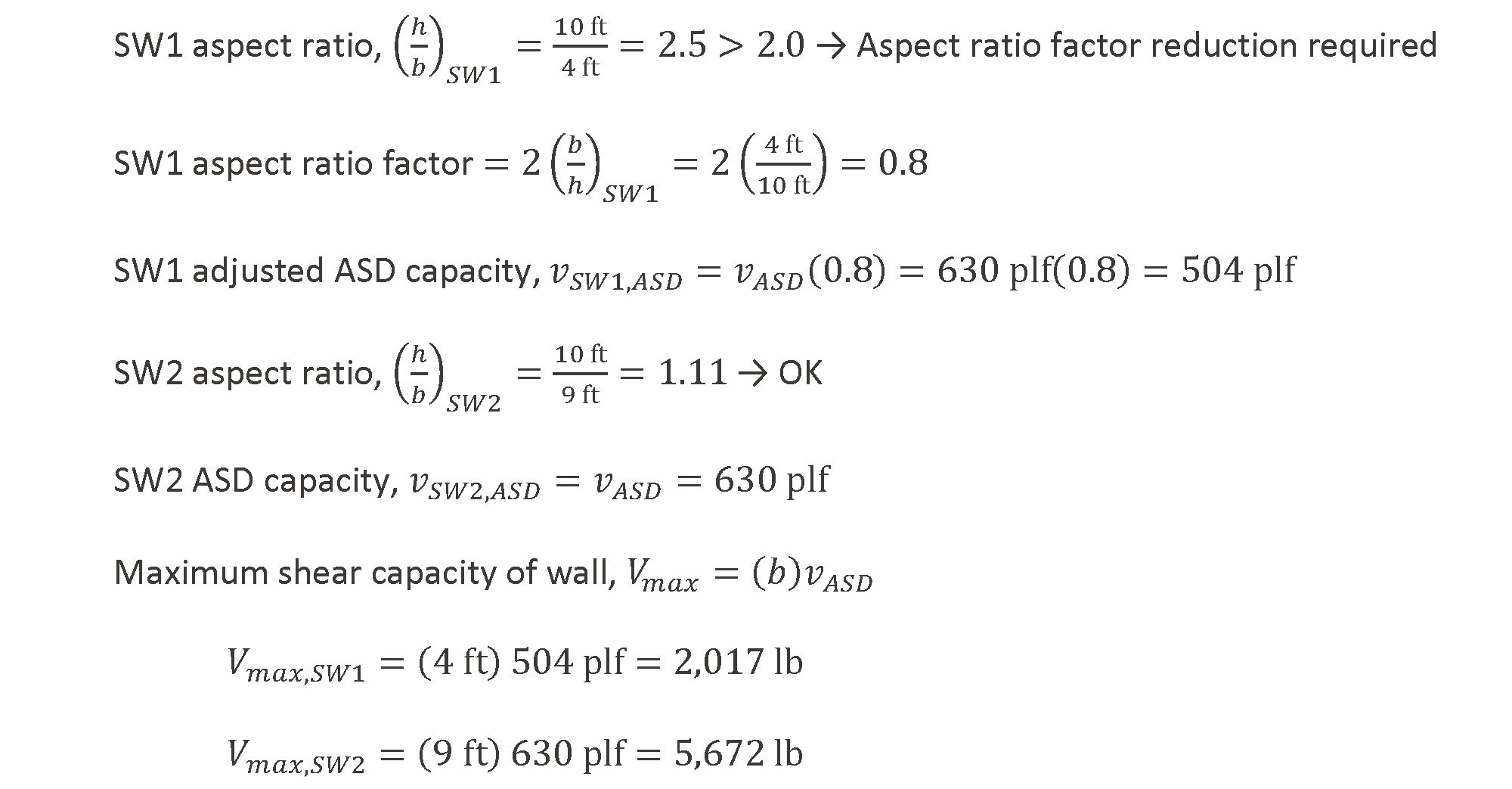
As with the first method, the first step in assessing the shear walls is to verify that the wall segments qualify for use. Again, this is done by comparing the wall segment aspect ratios to the maximums given in SDPWS Table 4.3.3 (Figure 3). However, with this approach, for walls with aspect ratios greater than 2:1, instead of using the typical reductions noted in Section 4.3.3.2, the wall capacities are reduced by the factors given in the Section 4.3.5.5.1 exceptions: 2b/h for WSP sheathing. These reductions, where required, account for the reduced stiffness of these walls.
Compare Combined Shear Wall Capacity to Shear Loading
In the simplified shear distribution method, the full capacity of the walls, as determined using the reduction factors discussed above, are allowed to be used and shear is distributed in proportion to the wall’s calculated strength capacity. Therefore, the next and final step is to compare the capacity of the shear walls along the line of resistance to the loading on the wall (Figure 6).

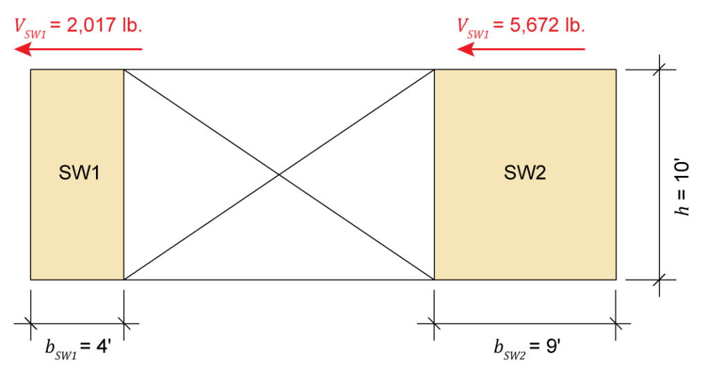
Figure 6: Shear wall capacities using the simplified shear distribution approach
Comparing the Two Approaches
Comparing the results of the two methods, we see that both calculations show that the proposed shear walls are acceptable for the given loading, with the simplified shear distribution approach resulting in slightly larger overall resistance. For this example, the longer shear wall, SW2, provides the same maximum resistance regardless of methodology; however, the shorter shear wall, SW1, provides less resistance in the equal deflection calculation approach than in the simplified shear distribution approach. This is because, in the simplified shear distribution approach, although the aspect ratio reductions are larger, 100% of the wall capacity is available to resist the load whereas, in the equal deflection calculation approach, only 61% of the wall capacity is available before the limiting deflection is reached. Even with the difference in the shorter wall capacity, because of the shorter length, this only results in a difference of about 8% in total resistance along the entire shear wall line.
End Note
- The wood-to-wood bearing amplification factors have traditionally been used for calculating shear wall deflections; however, application of the amplification factors is at the discretion of the Engineer of Record, based on framing type (e.g., modified balloon or platform) and design conditions (e.g., single-story, multi-story, etc.).