Expert Tips
Using Gun Nails in Wood-Framed Shear Walls and Diaphragms
Compares the calculated capacity of power-driven framing nails with tabulated shear wall and diaphragm capacities in the SDPWS
This article references the American Wood Council’s (AWC’s) 2024 National Design Specification (NDS) for Wood Construction and 2021 Special Design Provisions for Wind and Seismic (SDPWS).
Framers of modern light-frame wood buildings frequently use power-driven framing nails to fasten components in shear walls and diaphragms. A common question is whether these nails are equivalent to those specified in the NDS and SDPWS.
Background on Fasteners Specified in the NDS and SDPWS
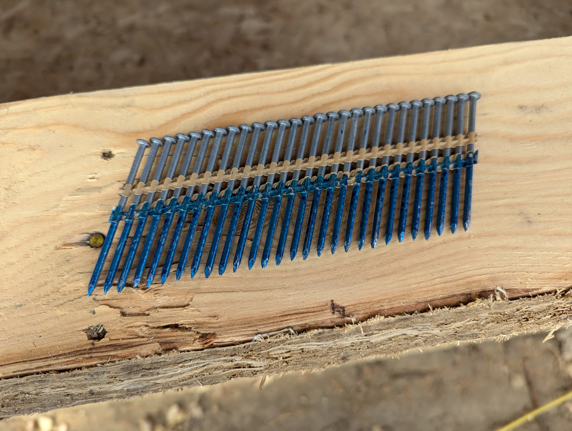
Section 12.1.6 of the NDS requires that nails comply with ASTM F1667: Standard Specification for Driven Fasteners: Nails, Spikes and Staples, which provides dimensions (shank diameter, length, and head diameter) for various nail types. These dimensions are summarized in Appendix L, Table L4 of the NDS and in Appendix A, Table A1 of the SDPWS (Figure 1) for nail types referenced by these two standards.
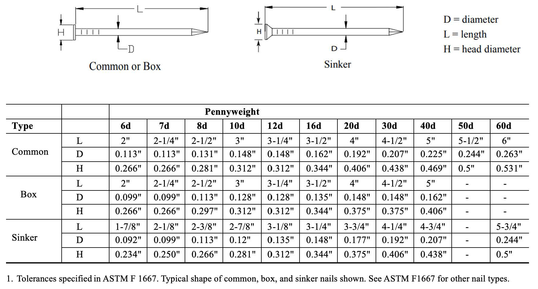
FIGURE 1: “Table A1 Standard Common, Box, and Sinker Nails” from SDPWS Appendix A denoting standard fastener dimensions
NDS Section 12.1.6 also requires that nails meet the supplementary requirements of ASTM F1667 S1: Nail Bending Yield Strengths. These yield strength requirements are provided in Appendix I of the NDS (Figure 2).
FIGURE 2: “Table I1 Fastener Bending Yield Strengths, Fyb” from NDS Appendix I denoting fastener bending yield strengths
Shear Capacities for Diaphragms and Shear Walls Using Specified Nails
Nominal unit shear capacities for wood structural panel diaphragms and shear walls are provided in SDPWS Chapter 4; diaphragm capacities in Tables 4.2A through 4.2D and shear wall capacities in Tables 4.3A through 4.3D.
In the 2021 SDPWS, diaphragm and shear wall capacity tables require the use of common nails, with dimensions explicitly noted. (Shear wall tables 4.3A and 4.3B also provide an alternative to use galvanized box nails per footnote 8.) However, in previous editions of the SDPWS, these tables refer to nails using the more generic “type” and “pennyweight” designations without explicitly stating the standard dimensions. NDS Appendix L and SDPWS Appendix A highlight the fact that, within a given pennyweight category (e.g., 8d or 10d), different nail types (e.g., common, box, or sinker) will have different dimensions. There are also many proprietary fasteners on the market that may have different dimensions than those listed in the tables. Therefore, when specifying nails for use in structural framing, designers should always include the intended dimensions (shank diameter, length, and head diameter).
Using Fasteners that Differ from SDPWS Specifications
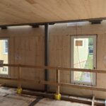
As noted, the SDPWS requires fasteners to comply with ASTM F1667, including the specified fastener dimensions and yield strengths. In practice, however, the fasteners used in power-driven tools such as nail guns often have smaller shank diameters, shorter lengths, and/or different head styles. Fastener dimensions are typically listed on the box containing the nails (Figure 3). When fasteners differ from those required by the SDPWS, capacities and other design information can often be found in third-party evaluation reports.
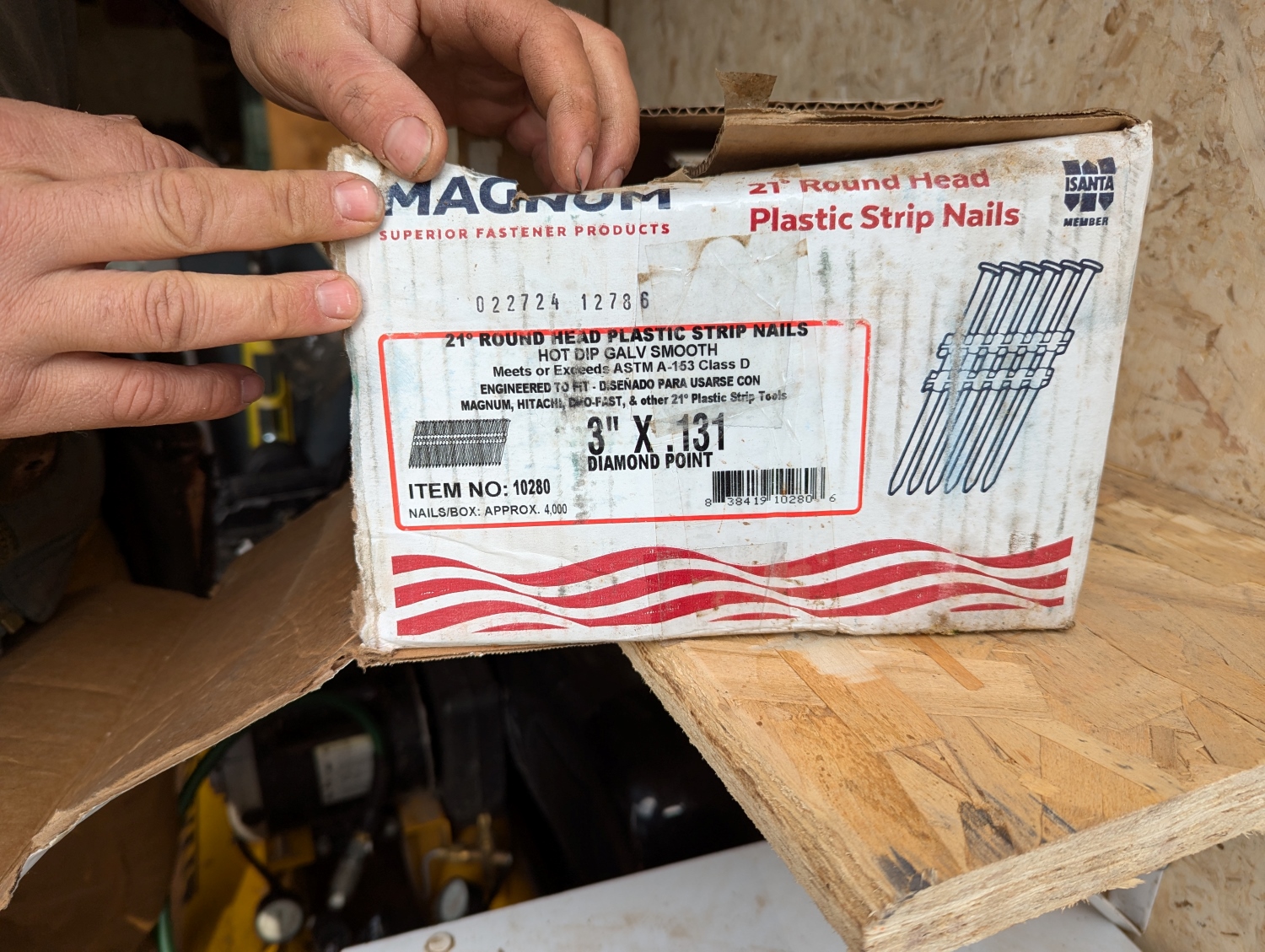
FIGURE 3: Fastener dimensions provided on a box of collated nails
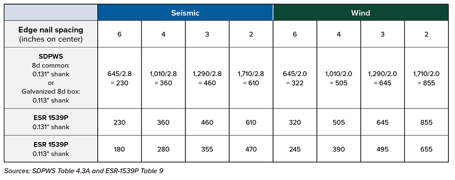
As an example of fasteners that differ from those required in the SDPWS, the International Staple, Nail and Tool Association (ISANTA) evaluation report, ESR-1539P: Power-Driven Staples and Nails covers nails of varying sizes and head styles intended for use in nail guns. Tables 7 through 10 of the ESR provide unit seismic and wind shear capacities for nails used in shear walls and diaphragms. Note that while SDPWS tables show nominal values, which need to be adjusted as appropriate for ASD or LRFD (see SDPWS Section 4.1.4), those listed in ESR-1539P are allowable values, which need no further adjustment for ASD.
Consider the tabulated design values for a shear wall using 3/8-inch wood structural panel (Structural 1) sheathing fastened with 8d nails. From SDPWS Table 4.3A, 8d common nails are required to be 2-1/2 inches long with a 0.131-inch shank diameter and a 0.281-inch-diameter head. Table 1 shows the nominal unit shear values in the SDPWS, adjusted to ASD seismic and wind capacities, and the capacities for nails in ESR-1539P, based on equivalent sheathing and nail shank diameter. For the same sheathing, nail shank diameter, and nail spacing, the SDPWS and ESR have the same design capacities, within minor rounding differences.
However, the ISANTA ESR includes nails shorter than those specified in ASTM F1667 and the SDPWS—e.g., a 0.131-inch shank diameter nail with a length as short as 2 inches. Using shorter nails that provide the minimum required fastener length of ESR-1539P Tables 7 through 10 will meet the SDPWS-required bearing length in the framing member. But if the nail length is less than the length required by the SDPWS, the capacities for these nails from the ESR are subject to approval by the jurisdiction as they are not SDPWS-compliant.
Footnote 8 of SDPWS Table 4.3A allows the use of a galvanized 8d box nail with a 0.113-inch shank diameter as a substitute for the 8d common nails with a 0.131-inch shank diameter; note that both of these nails are 2-1/2 inches long. To use this footnote, the galvanization needs to be hot-dipped (HDG) or mechanically deposited (MG). This does not include electro-galvanized (EG) nails. APA – The Engineered Wood Association’s TT-087, Shear Wall Test Results Comparing 8d Common and 8d Box Nails addresses this substitution:
In the 1960s, APA conducted 10 full-scale monotonic shear wall tests, comparing the performance of 6d and 8d hot-dipped galvanized box nails to that of 6d and 8d bright (uncoated) common nails (APA, 1988). Those tests showed that the hot-dip, galvanized box nails gave shear wall racking resistance that was approximately equal to that of shear walls assembled with common nails of the same pennyweight. This data was used to support the current provisions in the ANSI/AF&PA Special Design Provisions for Wind and Seismic (SDPWS) shear wall tables stating that the type of nail required is “common or hot-dip galvanized box.”1
However, shorter galvanized nails not meeting the SDPWS shank diameter and length requirements of the footnote require use of the lower design values provided by ESR 1539P instead of those specified in the SDPWS.
Whether for diaphragms or shear walls, the Structural Engineer of Record needs to be familiar with the various tables and to clearly specify which fasteners are intended for the project, including shank diameter, length, and head diameter, so design values match constructed values. On-site inspection of boxes of nails is recommended to verify that the correct nails are being used. Pre-construction meetings can also include discussions about which nails are appropriate.
Fastener Head Pull-Through
Nail fastener head pull-through, addressed in NDS Section 12.2.5, is a design consideration for instances such as calculating the uplift capacity of fasteners for a roof deck. Previous versions of the NDS did not consider nail head pull-through, only nail withdrawal. NDS equations 12.2-6a and 12.2-6b provide a way to calculate the pull-through design value (WH) of nails with standard round heads, while Table 12.2F tabulates reference pull-through design values for common head diameters. Reference values, whether from the table or calculated, must be adjusted per Section 11.3.
WH = 690 π DH G2 tns for tns ≤ 2.5 DH (12.2-6a)
WH = 1,725 π DH2 G2 for tns > 2.5 DH (12.2-6b)
Where:
π DH = Perimeter for fasteners with round heads, inches
DH = Fastener head diameter, inches
G = Specific gravity of side member
tns = Net side member thickness, inches
Many collated nail gun nails do not have standard round heads, but rather have offset round, D-head, or notched heads (Figure 4).
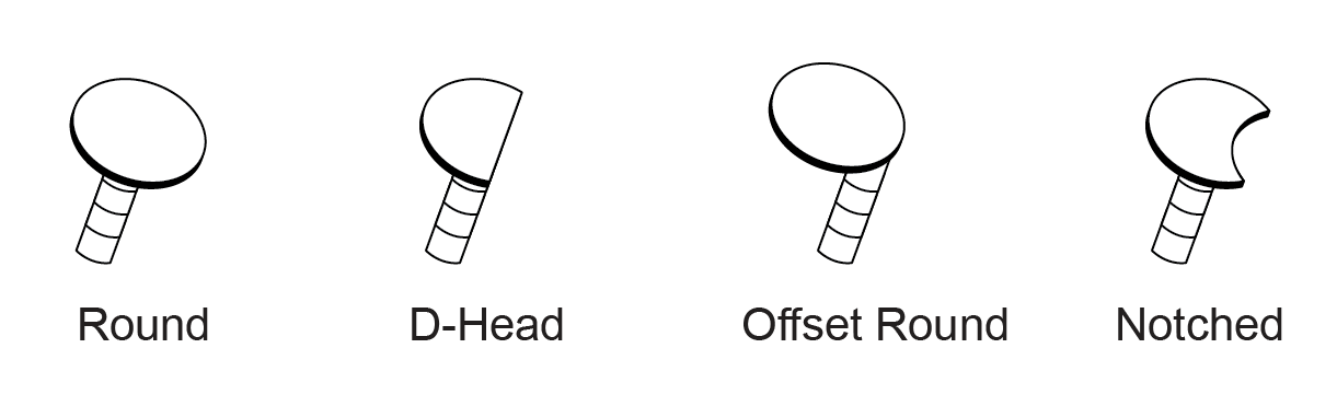
FIGURE 4: Nail head styles
Image courtesy ISANTA
For nail head pull-through in these situations, the NDS Commentary offers Equation C12.2.5-2:
WH = 690 PH G2 tns for tns ≤ 0.8 PH
Where
PH = Fastener head perimeter, inches
ISANTA discusses the issue further in their Technical Bulletin, Nail Head Pull-Through. A fastener uplift design example is also included.
Note that the guidance presented here is specific to the use of gun nails in shear wall and diaphragm applications. This article does not address fastener substitutions for connectors (e.g., joist hangers); use of alternative fasteners in these applications should be discussed with the connector manufacturer.
1While TT-087 was published in 2013 and references the 2012 NDS, 2012 SDPWS, and a previous version of ESR 1539P, the concepts described are still applicable.