
Expert Tips
Increasing Deck Diaphragm Capacities with Wood Structural Panels
Design and detailing considerations for designers seeking to increase the diaphragm capacity of lumber decking systems.
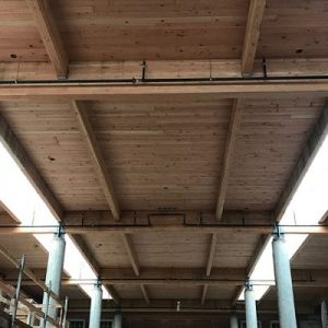
When designing wood-frame structures with lumber floor and roof decking, either new construction or modifications and rehabilitations of existing construction, the diaphragm capacity or aspect ratio of the lumber decking system may be inadequate and require reinforcing measures. The capacities of lumber diaphragms are given in Table 4.2D of the American Wood Council’s Special Design Provisions for Wind and Seismic (SDPWS). Additional options to evaluate the seismic capacity of existing lumber decking can be found in ASCE 41-13. A common method of increasing diaphragm capacities in this condition is to install a layer of wood structural panels (WSP)—i.e., plywood or OSB—on top of the lumber decking. In this condition, the lumber decking is no longer used as the structural diaphragm; the WSP layer is attached to the lumber decking and acts as a blocked diaphragm, using the capacities in SDPWS Table 4.2A.
While the WSP layer is resisting the diaphragm forces, the decking is acting in the same function that wall studs would in a shear wall or floor joists would in a diaphragm—providing common framing members for two adjacent panel edges to attach to in order to provide shear load transfer between panels. Field fasteners attach the sheathing to the decking to keep panels from buckling out of plane.
SDPWS Sections 4.2.7.1 and 4.2.7.1.1 provide specific requirements when using the WSP over lumber decking diaphragm condition. As noted, the diaphragm capacity of the decking is not used—only that of the blocked diaphragm consisting of the sheathing laid on top. Lumber decking, particularly when perpendicular to the supports, is a much more flexible diaphragm system than WSP diaphragms and does not effectively share load with the WSP diaphragm. One key detailing and construction item to keep in mind is that the sheathing panel edges must be offset from joints in the decking. This will require careful layout of the decking placement (in new construction) or careful layout of panels (in existing construction). Another consideration is whether minimum nail penetration values into the decking can be met. For example, if the lumber decking is only 1x (3/4″ actual thickness) or 2x (1-1/2″ actual thickness), nails used to attach the WSP to the decking may only be 1-1/2″ long, meaning the minimum nail penetration of SDPWS Table 4.2A may not be able to be met. APA Report TT-097 provides a summary of considerations and APA Report TT-061provides information for the condition of inadequate nail penetration. This report suggests that only 1.0″ of penetration is required for 8d nails to achieve full diaphragm capacity. As this may not meet the minimum nail penetration of SDPWS Table 4.2A, discussion with the building official may be prudent.

Once the standard diaphragm capacity has been determined and fastener schedules set, the boundary of the diaphragm must be designed. At these locations, the diaphragm forces need to be taken out of the sheathing, through the decking, potentially into the boundary framing members (depending on how the floor/roof is framed) and then into the vertical lateral force-resisting systems below. The attachment of the decking to the diaphragm boundary framing members (or directly to the vertical lateral force-resisting system) is designed for the unit diaphragm reaction along that line, or the chord force, whichever is greater. This is typically done with common fasteners (e.g., nails, screws, etc.). The required minimum spacing of the fastener being used is determined using the diaphragm shear load or diaphragm capacity per unit length of the connection.
Related Resources
-
 Hybrid Design: Mass Timber Floor and Roof Panels Over Light-Frame Wood Walls Expert Tips
 -
 Architectural Finishes and Mass Timber: A Primer Expert Tips
 -
 The Modular Enclosure: Protect Your Investment During Every Phase Expert Tips
 -
Exterior Walls in Mass Timber Buildings – Part 1: Code Requirements and Commonly Used Materials Expert Tips